Hot
EMERGENCY
Line Voltage (120-277VAC)
GRAY
0-10V Ground
VIOLET
0-10V
dimming
Control
RED Switched Load
120-277VAC
WHITE Neutral
VIOLET 0-10V
Wireless Adapter with Power Monitoring
Model: WA100-PM
Input: 120-277VAC, 50/60 Hz
Load: 15A@120-277VAC Ballast or Incandescent, 1hp@120-230VAC
Output: +24VDC; 75mA
Ambient Temperature -4° to 149°F (-20° to 65°C)
FOR INDOOR USE ONLY UL 2043 Plenum Rated
Patent: www.daintree.net/company/patents
C
US
IEEE Address: 00228103007-00000
Load
Black
Hot
Neut
Red
White
Blue (Digital In 1)
Yellow (Digital In 2)
Orange (0-10V In)
Red (24VDC Output)
Black (Ground)
Green (Digital Out LSD)
Violet (0-10V Out)
Gray (Ground)
Relay
WA100-PM
15A
15A+45mA
45mA
CONTAINS FCC ID: Z6G-DT357
CONTAINS IC: 10478A-DT357
CAN ICES-3 (B)/NMB-3(B)
RoHS
WA100-PM
REGULAR
Line Voltage
(120-277VAC)
LVS Model RRU-X-UM
NC
COM
NO
WHITE
Neutral
Hot
*
NC
COM
NO
RED
BLACK
BLUE
RED
BLUE
YELLOW
*
Connect
120VAC to BLK
277VAC to ORG
FIXTURE
LED Driver or
Electronic Dimming
Ballast (0-10VDC)
BLACK Hot
WHITE Neutral
Wiring to
bypass WA100
Line Voltage
and Dimming
control to
power failure
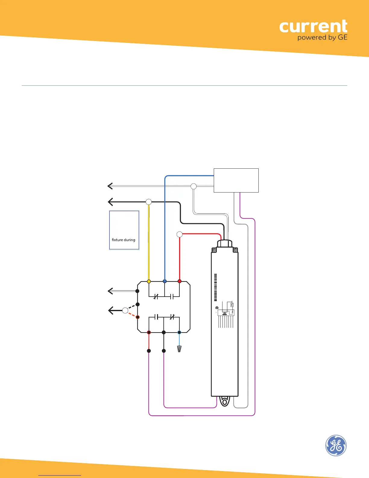
Wireless Adapter (WA100-PM)
In the wiring diagram here, while Regular power is supplied to the LVS model RRU-X-UM the WA100-PM provides
switched On/Off power and 0-10V dimming control to the fixture driver or ballast.
When the RRU-X-UM senses loss of Regular power it passes Emergency power directly to the fixture.
It disconnects the WA100-PM switched output and disconnects the WA100-PM dimming control so that the fixture will
operate at maximum output during the power failure.
Fig. 16: Bypass WA100 switched power and 0-10V dimming control during power failure
18