CURTMFG.COM
•
NEED ASSISTANCE?
•
87 7. 2 8 7. 8 6 3 4
•
52040-INS-RB
•
PAGE 2
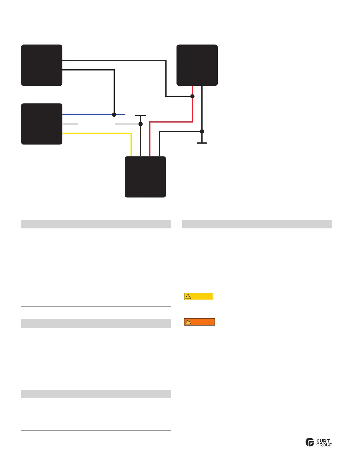
WIRING DIAGRAM
Breakaway
Switch
12V (+) - Black
12V (+) - Red
12V (-) - Black
12V (+) - Yellow
Trailer Brakes
Black
Brake Control
Output - Blue
Trailer Chassis
Ground
Trailer Chassis
Ground
Trailer
Connector
Push-to-Test
Panel
12V Trailer
Breakaway
Battery
Pos (+)
(-) Neg
12V (-) - White
Step 2 - Wiring
Connect one of the black wires to the
breakaway battery's positive (+) terminal.
Splice the other black wire to the
blue wire leading to the trailer brakes.
Note: The blue wire should show 12V positive
when the vehicle brakes are applied.
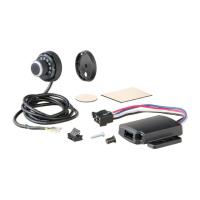
Step 1 - Mounting
Position the breakaway switch on the tongue of the trailer so that it
allows the cable to reach the tow vehicle's trailer hitch safety chain
eyelets. This is critical for proper engagement of switch.
Identify a suitable mounting location and drill a 9/32" hole in the
trailer frame to mount the breakaway switch. Use the provided
hardware to mount the switch to the trailer Note: Use caution when
drilling the hole, making sure there are no wires or other objects
behind the drilling surface. Do not to over-tighten the bolt so the
breakaway switch can pivot.
Find a suitable location on the trailer frame to mount the battery case.
Mount in a location that it does not interfere with the switch's lanyard.
Step 3 - Wiring
Splice yellow wire on breakaway
box to trailer 12V auxiliary power lead.
Splice white wire of the breakaway box to the white
ground wire coming from the trailer side connector.
Prior to Towing
Prior to each use, check the system's battery for operating voltage.
Check that the breakaway switch cables are not damaged from
dragging on the ground and that they can move freely.
Check the breakaway system periodically to ensure proper and secure
connections. Open and / or short circuits may result in a no-brake situation.
Test the breakaway by pulling firmly on the cable of the breakaway
switch. The battery will activate the brakes. Note: Do not use this kit
as a parking brake. Ensure battery is charged prior to each use.
Do not attach the breakaway switch cable to
mounting hooks, trailer safety chains or the trailer ball.
WARNING
In order to avoid severe damage to the tow vehicle's electric brake
controller, disconnect the trailer connector from the tow vehicle prior
to testing the breakaway system.
 Loading...