EasyManua.ls Logo

curt 58902 - User Manual

curt 58902
3 pages
Print Icon
To Next Page IconTo Next Page
Loading...
58902-INS-RA
PAGE 1
INSTALLATION MANUAL
Level of Difficulty
Moderate
Product Photo
Included Parts
Product Registration and Warranty
CURT Group stands behind our products with industry-leading warranties.
Provide feedback and help us to improve our products by registering your purchase at:
warranty.curtgroup.com/surveys
Maintenance
Periodic inspection of all wires and connections should be performed
to ensure there is no visible damage or loose connections.
Electrical Ratings
Signal circuits 7.5-amps per side
Tail / Running Circuits 7.5-amps total
Check vehicle owner's manual or contact
the vehicle manufacturer for more information.
NOTICE
Before you begin installation, read all instructions thoroughly.
Proper tools will improve the quality of installation and reduce the time required.
All steps must be followed to ensure the product will function properly. Once installed,
test for proper function by using a test light or connecting a properly tow vehicle.
WARNING
Do not exceed product rating or tow vehicle lamp load rating, whichever is lower.
Wiring Location Guide*
for SUVs and Vans (S)
S1 Behind driver side taillight housing
S2 Behind passenger side taillight housing
S3 Behind driver side rear access panel
S4
Behind passenger side rear access panel
S5 Behind driver side rear bumper
S6 Behind center of rear bumper
S7 Behind passenger side rear bumper
S8 Under rear floor panel
S9 Behind driver side rear access panel
S10
Behind passenger side rear access panel
S5 S6 S7
S1
S3
S8
S4
S2
S9
S10
* Representative vehicle shown
Wiring Location(s)
S5 and S7
Tools Required
Ratchet Socket, 10mm
Flathead screwdriver Utility knife
Question and Answer IconNeed help?

Do you have a question about the curt 58902 and is the answer not in the manual?

Summary

Level of Difficulty

Warning

Electrical Ratings

Wiring Location(s)

Wiring Location Guide for SUVs and Vans

Lists specific wiring harness connection points for SUVs and Vans.

Tools Required

Notice

Maintenance

Product Registration and Warranty

Installation Steps

Step 1: Driver-Side Taillight Removal

Remove screws securing the plastic lens cover on the driver-side taillight using a Phillips screwdriver.

Step 2: Taillight Removal and Connector Inspection

Remove taillight bolts, detach connectors, and inspect for debris. Repeat for passenger side.

Step 3: Harness Connection and Shielding

Insert RV harness end with yellow wire between separated connectors and ensure secure connection.

Step 4: Grounding Point Preparation

Locate a suitable grounding point, clean it, and secure the white ground wire with the provided screw.

Step 5: Routing Harness to Passenger Side

Route the RV harness end with green wire to the passenger side along the rear frame rail.

Harness Routing and Securing

Step 6: Cable Tie Management

Cut cable ties on the 4-flat portion and route it down behind the taillight, securing with provided ties.

Step 7: Continued Routing

Continue routing towards the front, following factory wiring and securing with cable ties.

Step 8: Routing to Engine Compartment

Route the 4-flat wire up brake lines and along factory harness to the hood release area.

Step 9: Bracket Mounting

Drill mounting holes for the 4-flat bracket behind the driver-side taillight and attach with screws.

Step 10: Final Securing and Reassembly

Secure excess wire, reinstall removed items, reconnect battery, and install dust cover.

Overview

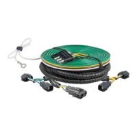
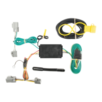
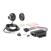
This document outlines the installation process for a wiring harness designed to provide electrical connections for towing, likely for a trailer or other towed vehicle. The product is a wiring harness that connects to the vehicle's existing taillight wiring to provide standard 4-flat trailer light functions.

Function Description

The device is a trailer wiring harness that allows a vehicle to power the lights of a towed trailer. It integrates with the vehicle's existing taillight wiring system to provide the necessary electrical signals for tail lights, running lights, and turn signals on the trailer. The installation involves connecting the harness to the vehicle's taillight circuits on both the driver and passenger sides, routing the wiring along the vehicle's frame, and securing a ground connection. The final output is a 4-flat connector, a common standard for trailer wiring, which provides power for stop, turn, and tail lights. The harness is designed for SUVs and Vans, with specific wiring locations indicated for different access points.

Important Technical Specifications

  • Level of Difficulty: Moderate, suggesting that while some mechanical aptitude is required, it's generally manageable for a DIY installer.
  • Electrical Ratings:
    • Signal Circuits: 7.5 amps per side. This refers to the maximum current draw for turn signals and brake lights on each side of the trailer.
    • Tail / Running Circuits: 7.5 amps total. This refers to the maximum current draw for the tail and running lights of the trailer.
  • Warning: It is crucial not to exceed the product's rating or the tow vehicle's lamp load rating, whichever is lower, to prevent electrical damage or failure.
  • Tools Required:
    • Ratchet
    • Socket, 10mm
    • Phillips screwdriver
    • Flathead screwdriver
    • Utility knife
  • Included Parts: The manual shows a wiring harness with multiple connectors, a ground wire with a ring terminal, a 4-flat connector, and a bracket. It also includes cable ties and a dust cover for the 4-flat connector.

Usage Features

  • Integration with Vehicle Taillights: The harness directly taps into the vehicle's existing taillight wiring, simplifying the connection process by utilizing pre-existing circuits.
  • Standard 4-Flat Output: Provides a widely compatible 4-flat connector, suitable for most light-duty trailers.
  • Driver and Passenger Side Connections: Requires connections on both sides of the vehicle's rear to capture all necessary signal inputs.
  • Grounding Requirement: A dedicated ground connection is essential for proper operation, typically secured to the vehicle frame.
  • Cable Management: The installation guide emphasizes securing the harness with cable ties along the vehicle's frame and existing wiring to prevent damage and ensure a tidy installation.
  • Dust Cover: A provided 4-flat dust cover helps protect the connector from corrosion and environmental elements when not in use.
  • Safety Warnings: Includes warnings about checking for hidden items before drilling and avoiding routing wires near moving, hot, or sharp parts to prevent damage or injury.

Maintenance Features

  • Periodic Inspection: The manual recommends periodic inspection of all wires and connections to ensure there is no visible damage or loose connections. This proactive maintenance helps ensure continued reliable operation.
  • Corrosion Prevention: The inclusion of a 4-flat dust cover is a key maintenance feature, designed to prevent corrosion of the electrical contacts when the connector is not in use, thereby extending its lifespan and ensuring consistent electrical connection.
  • Re-application of Foam Tape: Instructions to re-apply foam tape after connecting the harness help maintain the vehicle's original sealing and protection against elements.
  • Testing After Installation: It is advised to test the product for proper function using a test light or by connecting a properly wired tow vehicle after installation. This ensures that all connections are correct and the system is operational.

curt 58902 Specifications

General IconGeneral
Brandcurt
Model58902
CategoryAutomobile Accessories
LanguageEnglish

Related product manuals