EasyManua.ls Logo

curt 52040 User Manual

curt 52040
2 pages
To Next Page IconTo Next Page
Page #1 background imageLoading...
Page #1 background image
CURTMFG.COM
NEED ASSISTANCE?
87 7. 2 8 7. 8 6 3 4
52040-INS-RB
PAGE 1
INSTALLATION MANUAL
52040
Product Photo
Level of Difficulty
Easy
WARNING
Never exceed the vehicle manufacturer's recommended towing capacity.
In order to avoid severe damage to the tow vehicle's electric brake controller, disconnect
the trailer connector from the tow vehicle prior to testing the breakaway system.
CAUTION
Do not attach the breakaway switch cable to
mounting hooks, trailer safety chains or the trailer ball.
Maintenance
Prior to each use, check the system's battery for operating voltage. Check that the breakaway
switch cables are not damaged from dragging on the ground and that they can move freely.
Check the breakaway system periodically to ensure proper and secure connections.
Open and / or short circuits may result in a no-brake situation.
Test the breakaway by pulling firmly on the cable of the breakaway switch.
The battery will activate the brakes. Note: Do not use this kit as a parking brake.
Ensure battery is charged prior to each use.
NOTICE
Before you begin installation, read all instructions thoroughly.
Proper tools will improve the quality of installation and reduce the time required.
To help prevent damage to the product or vehicle, refer to the specified
torque specifications when securing hardware during the installation process.
Parts List
1 Breakaway switch
1 Battery case
1 Battery charger
1 Battery, 12V 5Ah gel cell
4 Self-tapping screw with
hex head washer, 1/4"-14 x 3"
4 Flat washer, 5/16"
4 Nylock nut, 5/16"
2 U-bolt, 5/16"
Tools Required
None
Product Registration
CURT Group stands behind our products
with industry-leading warranties. Provide
feedback and help us to improve our
products by registering your purchase at:
warranty.curtgroup.com/surveys
Battery Charging
If the system measures voltage less
than 14V, the charging circuit will provide
maximum charging current to a 12V 5Ah
gel cell battery until the battery is fully
charged to 14V. During the operation,
the system provides a trickle charge
to maintain battery voltage.
When battery voltage is under 6V, relay
K1 will not activate when switch S1 is
activated and the whole tester circuit
will have no power and will not activate
either the green or red LED. This will
indicate a dead battery.
This breakaway kit is designed to activate
the trailer's electric brakes if the trailer
should disconnect while towing, bringing
the trailer to a safe stop. Breakaway kits
are required when towing trailers of
3,000 lbs. GTW or greater.
Note: Your trailer must be equipped with
electrical brakes in order to use this kit.
Question and Answer IconNeed help?

Do you have a question about the curt 52040 and is the answer not in the manual?

curt 52040 Specifications

General IconGeneral
BrandCURT
Part Number52040
FinishPowder Coated
MaterialSteel
Weight Capacity10000 lbs

Summary

Safety and Notices

WARNING

Never exceed the vehicle manufacturer's recommended towing capacity. Disconnect trailer connector prior to testing.

CAUTION

Do not attach the breakaway switch cable to mounting hooks, trailer safety chains, or the trailer ball.

NOTICE

Read all instructions thoroughly before installation. Use proper tools for quality and time reduction.

Battery Charging

Charging System Operation

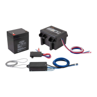
System provides maximum charging current to a 12V 5Ah gel cell battery until fully charged to 14V, then trickle charges.

Low Voltage Indicator

Voltage under 6V prevents relay activation and circuit power, indicating a dead battery.

Maintenance and Testing

Maintenance Checks

Check battery voltage, cable condition, and connections periodically for proper operation.

Breakaway Switch Test

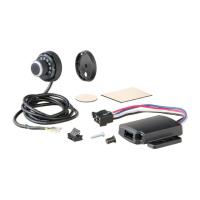
Pull breakaway switch cable firmly to activate brakes. Do not use as a parking brake. Ensure battery is charged.

WIRING DIAGRAM

Step 1 - Mounting

Position breakaway switch for cable reach to hitch eyelets. Drill 9/32" hole for mounting. Mount battery case.

Step 2 - Wiring

Connect black wires to battery positive and splice to trailer brakes (blue wire for 12V positive).

Step 3 - Wiring

Splice yellow wire to trailer 12V auxiliary power and white wire to trailer ground.

Prior to Towing

Check battery voltage, cable condition, and connections. Test breakaway switch operation.
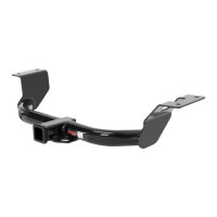
Related product manuals