iii
Curtis 1212S Manual, R ev. B
FIGURES
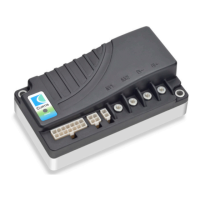
fig. 1: Curtis 1212S electronic motor controller ................................. 1
fig. 2: Mounting dimensions, Curtis 1212S controller ....................... 4
fig. 3: Standard wiring configuration, 1212S controller ...................... 6
fig. 4: Wiring for 5kΩ, 3-wire potentiometer ..................................... 7
fig. 5: Wiring for voltage throttle ....................................................... 7
fig. 6: Effect of adjusting the Throttle Map parameter ..................... 15
fig. 7: Wiring for Pump SRO ........................................................... 21
fig. B-1: Safety channel block diagram ................................................. 38
TABLES
table 1: Programmable parameter menus ....................................... 10
table 2: Troubleshooting chart ....................................................... 33
table E-1: Specifications, 1212S controllers ....................................... 44

 Loading...