Curtis 1212S Manual, R ev. B
5
2 — INSTALLATION & WIRING
J1 Pin 1
Pot Wiper
J1 Pin 2 Pot High
J1 Pin 3 Lift Lockout Output
J1 Pin 4 Mode Switch (open=M1, closed=M2)
J1 Pin 5 Keyswitch Input (KSI)
J1 Pin 6 Interlock Input
J1 Pin 7 B+
J1 Pin 8 Pot Low
J1 Pin 9 Lift Lockout Input / Pump SRO input
J1 Pin 10 Forward Input
J1 Pin 11 BDI Output (0–5V)
J1 Pin 12 Reverse Input
J1 Pin 13 I/O GND
J1 Pin 14 Emergency Reverse
CONNECTIONS: High Current
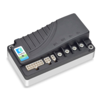
Four M4 bolt-on power terminals are provided for the high current connections:
two for the motor
(M1, M2) and two for the battery (B-, B+). The recommended
assembly torque for the M4 bolts is 1.6±0.2 N.m.
CONNECTIONS: Low Current
The low current logic control connections are provided by a 14-pin connector.
A 4-pin low power connector is provided for the programmer and the charge
inhibit input, and a 2-pin low power connector for the electromagnetic brake.
J2
J2 Pin 1 Rx
J2 Pin 2 I/O GND
J2 Pin 3 Tx/charge inhibit
J2 Pin 4 +15V
J3 Pin 1 Brake +
J3 Pin 2 Brake -
1
2
J3
J1
1234567
8910 11 12 13 14
The mating connectors are:
J1 Molex Mini-Fit-Jr. receptacle p/n 39-01-2140
J2 Molex Mini-Fit-Jr. receptacle p/n 39-01-2040
J3 Molex Mini-Fit-Jr. receptacle p/n 39-01-2020,
all with appropriate 45750-series crimp terminals.

 Loading...