12
power to the valve solenoid and the valve does not open.
Replace the board.
III. If both the probe and the liquid level control board are
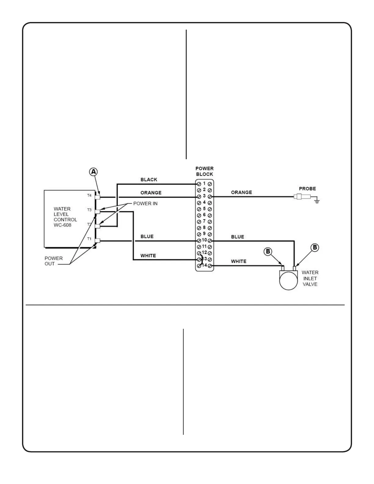
functioning normally, check the water inlet valve.Turn
on the unit and disconnect the white and the blue wires
from the coil on the valve (points Bofgure9).Usea
lamp cord with alligator clips; hookup the terminals to
the cord. Plug the cord into a 120 volt outlet. The valve
should open when plugged in and close when unplugged.
Repeat this three or four times. If you don’t hear the
sound of the solenoid, then the coil is bad. If you hear
waterowingthroughthevalvewhenunplugged,the
diaphragm is either torn or needs cleaning. Replace the
coil, diaphragm or clean out the valve.
Figure 9. Water Level Control System.
the quick disconnect terminal attached to the orange
wire and with the other lead of the meter, touch the metal
surface of the urn shell. Any reading in the meter dial will
indicate the presence of a ground in either the terminals,
wire, or probe assembly. Find the ground and repair it. If
there is no reading at all on your ohmmeter, the probe is
okay. Return the orange wire to the terminal 4 of the liquid
level control board where it was removed.
II. Turn the unit on and clamp the leads of your voltmeter at
the terminals of the valve coil as shown at Bofgure9.
Under normal conditions, the voltmeter should read 110
to120voltswhiletheurnisllingupandpowertothe
coil should stop once the water level reaches the probe
tip. If the voltmeter does not show voltage, the liquid level
control board is not working properly. It is not sendin
BREWING OPERATION
Components Involved: Fuse, Brew Switch, Hold-
ing Relay, Timer, Stop Switch and Water Pump.
PROBLEM: Brew switch light does not turn on
when pressed.
Test: Check your power supply and fuse in con-
trol box. It may be burned out.
Problem: Brew switch does not stay on, or light
stays on only while switch is pressed but turns
off when released and water comes out of spray
head only while the switch is kept pressed.
Test Brew Switch: Take a voltage reading at
points A of Fig. 10 while the brew switch is
pushed in. If you read 110 volts, that means the
switch is good.
Also, read voltage at points B of Fig. 10 to see if
the coil of holding relay is being energized.
Test Holding Relay: The relay is used to ener-
gize the water pump, and the timer, therefore a
simple voltage reading across C in the terminal
strip will show if the relay is opening and closing
its contacts. A zero reading will indicate a faulty
relay. By the process of elimination, so far we
established that the brew switch, and relay are
working properly but the problem still remains.
Test Timer: The timer resets itself to the N. C.
 Loading...