13
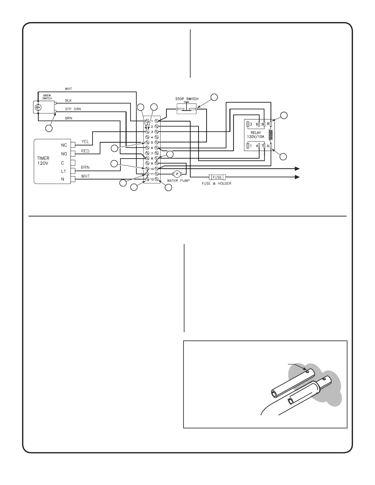
position after every brewing cycle but if it fails to
stop itself, it will remain open and cause the prob-
lem in question. To check the timer, disconnect
yellow and red wires at E and take a continuity
test between the two wires. If there is no continu-
ity, the switch is open and must be replaced.
Test Stop Switch: The last of the components in-
volved in this operation is the stop button. Its only
function is to interrupt the current that energizes
the coil of the holding relay after the brew switch
has been depressed. A voltage reading at points
F will indicate an open or closed condition.
AERATION SYSTEM
Components Involved:
1. Aeration Switch
2. Holding Relay
3. Air Pump
AUTOMATIC AERATION
PROBLEM: Only one of the liners is aerated.
TEST: Inside the control box, there are two
silicone tubes connecting the aeration pump to
the ¼” copper tubes coming from inside the urn.
Carefully, pull the silicone tubes from the cop-
per tubes, press the manual aeration button and
using your hand, feel for air pumping out from the
silicone tubes. Determine if the pump is working.
Replace the pump if air does not blow through the
tubes.
These are air release holes
so that after air is pumped
into the liner, coffee can
rell the gauge glass.
NOTE: When replacing the silicone tubing on the
copper tubes, make sure you do not cover the
small holes on the copper tubes.
MANUAL AERATION
PROBLEM: Manual aeration is not present on
either of the liners, yet automatic aeration operates
normally.
TEST: Check the continuity of the manual aera-
tion switch. Check to see that the BLACK wire runs
from terminal 1 of terminal strip #1 to the switch and
YELLOW wire runs from the switch to terminal strip
#2. Check for clean, tight connections at all termi-
nals.
L1
L2
TO POWER
BLOCK, CORD OR
TRANSFORMER
B
C
C
A
A
B
B
D
D
E
E
F
Figure 10. Brewing Operation
F
Figure 11. Air Pump Tubes.
 Loading...