11
TROUBLESHOOTING
To help the service technicians in the eld to
understand the operation of the RU models, we
separate the basic functions of the unit into four
different areas:
1. Heat Supply
2. Water Level Control
3. Brewing Cycle
4. Aeration
These four functions, even though they utilize
the same power supply, work independently from
each other.
In the following illustrations, problems are isolated
to only that system where a malfunction is locat-
ed, so in the eld or shop, you will know exactly
what components are involved.
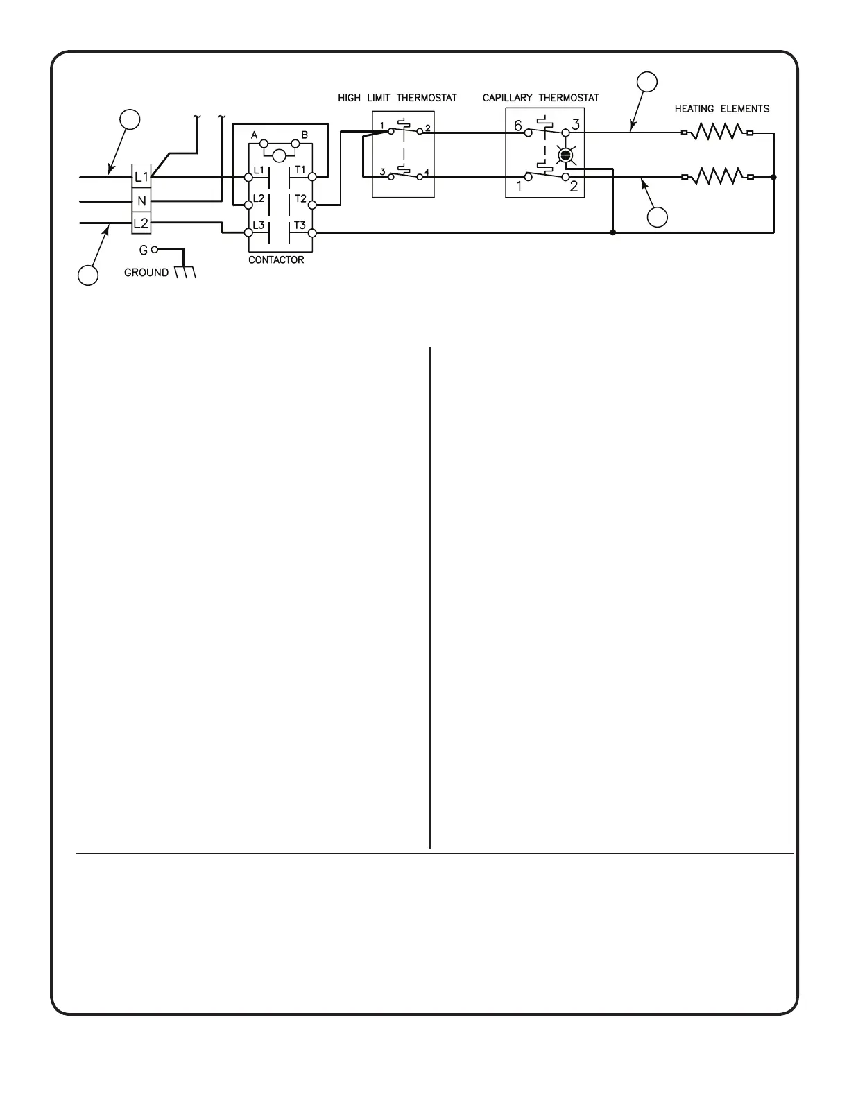
HEAT SUPPLY OPERATION
Components involved:
1. Power Block
2. Thermostat
3. Heating Elements
HEAT SUPPLY
PROBLEM: Water will not heat up or heats up
too slowly.
PROCEDURE: Take a voltage reading at termi-
nals 1 and 3 of the power block to see if there is
power from lines 1 and 2. If there is power at the
power block, turn the thermostat all the way to
boil and clamp your ammeter around line 1 or 2 at
point A shown in gure 8. The reading should be
approximately the same as indicated in the serial
plate of the machine.
If you do not get a reading on your ammeter,
remove the bottom cover of the urn and check
for voltage at terminals 1 & 6 and 2 & 4 of the
thermostat. If there is voltage at 1 and 6 (with the
thermostat turned to boil) and there is no voltage
at terminals 2 and 4, replace the thermostat.
If the meter reads only half of the amps that
your urn is rated at (check serial plate), one of
the heating elements has burnt out. Clamp your
ammeter at points B (see gure 8, above) to
determine which of the heating elements is bad.
Replace the heating element.
If the water temperature in the urn is too hot (boil-
ing) or too cold when the pilot light goes out, the
thermostat must be recalibrated. Reset the ther-
mostat calibration, refer to the steps on page 2.
If the thermostat will not hold a calibration, re-
place the thermostat.
Figure 8. Single Phase Power Hookup. For Three Phase see Wiring Diagram.
WATER LEVEL CONTROL OPERATION
Components Involved:
1. Probe Assembly
2. Liquid Level Control Board
3. Water Inlet Valve Assembly
PROBLEM: Water does not go into the urn jacket.
PROCEDURE:
I. Turn off the unit and test the probe assembly and
check for grounded wiring. Pull orange wire from
terminal 4 of the liquid level control board at point A
 Loading...