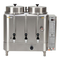
UNPACKING THE URN
All urns are carefully packed in cartons with lami-
nated cardboard inserts. The packaging is speci-
cally to tted to your urn. The packaging exceeds
the requirements of the I. C. C. regulations.
Inspect all containers at the time of delivery for
visual or concealed damage. In case of punctured
or damaged cartons the carrier must be notied im-
mediately.
2
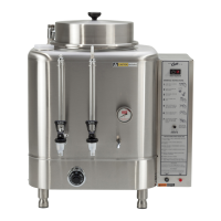
URN ASSEMBLY & INSTALLATION
Attach adjustable legs, screwing them into the four corners beneath the urn. Locate the urn on a sturdy,
level countertop. Install the water and coffee faucets.
WATER SUPPLY
All Curtis Automatic Urns are equipped with a ¼” male are tting which must be connected to the water
supply with a ¼” copper tubing and a ¼” are nut. It is recommended that some type of water strainer be
used in the water line before entering the unit. We advise using a mineral reducing lter. To expedite the
lling of the urn, you may use the emergency rell valve.
CAUTION Don’t forget to close the valve once it lls.
HEAT SUPPLY
Read the serial plate to determine the energy source of the urn (electric, gas, steam).
WARNING When you hookup an electric urn, use the proper wire gauge, plus 25%. Never use fuses or
breakers larger than needed. The body of the urn must be securely grounded with a separate grounding
conductor and never with the neutral conductor of a single phase, 3 wire system. Refer to the wiring diagram
included with each urn for wire gauge.
ITEM QTY TWINQTY SINGLE
WIRE BASKET
LID WITH KNOB
FAUCET, HOT WATER
FAUCET, COFFEE
LEGS, ADJUSTABLE
FILTERS, PAPER
SERVICE MANUAL
1
1
1
1
4
25
1
2
2
1
2
4
40
1
PACKING LIST
ELECTRIC THERMOSTAT ADJUST
On electric urns, thermostats are set at the factory to cut off at 200ºF. We do not recommend changing this.
If necessary, adjustment is as follows:
1. Rotate the thermostat knob to the right to the BOIL position. Pull off the knob.
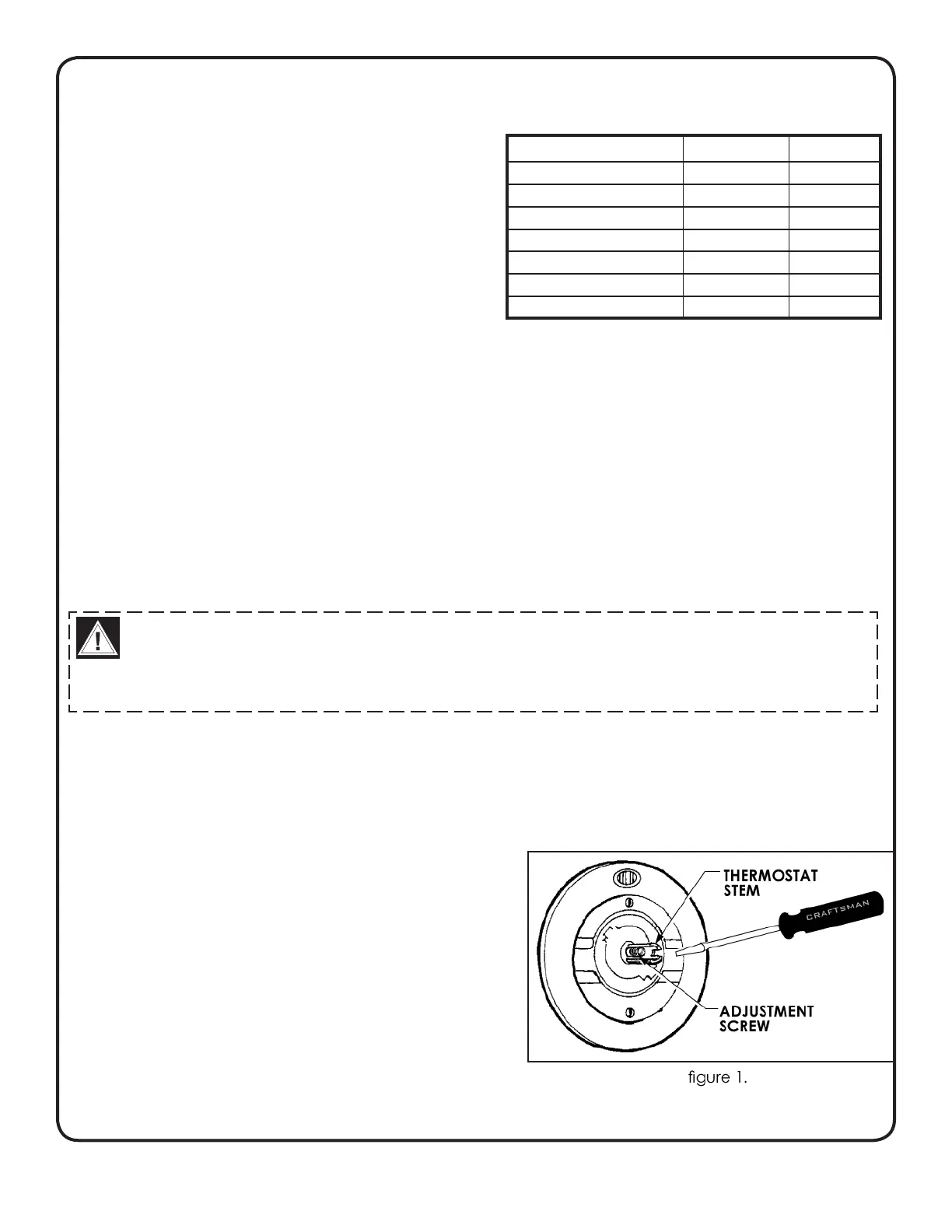
2. Locate the tiny adjustment screw, inside the stem (see
gure 1). Using a small screwdriver, adjust the tem-
perature up or down:
a. By turning the screw ¼ turn to the left will increase
the temperature about 20°F.
b. Turning the screw ¼ turn to the right will decrease
the temperature by 20°F.
c. To set the thermostat precisely at 200°F, insert
a thermometer probe into the water jacket through
the steam hole (just under the sprayhead). Turn
the screw ½ turn to the left. When the thermometer
reaches 200°F, slowly turn the adjustment screw to
the right until the pilot light turns off.
INSTALLATION AND OPERATING INSTRUCTIONS
 Loading...