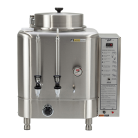
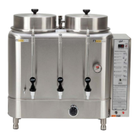
GAS URN INSTALLATION
The urn must be away from wall no less than 6”
and must have plenty of cross ventilation.
The water supply connection is the same in all RU
models. All that is needed is 1/4” copper tubing
with a 1/4” are nut and some sort of water lter
in the line before water enters the unit. Once the
water connection is complete, open the water line,
then plug in the power cord into an 115V outlet.
To facilitate the lling of the water jacket, you
can open the emergency rell faucet (red knob)
behind the unit, to increase the speed of lling the
urn. Water must be above the base of the center
gauge glass before turning on the heat.
IMPORTANT Be sure to shut off the
emergency rell valve after lling to
prevent overow!
GAS CONNECTION
All RU automatic urns are supplied with a
3/8” pressure connector at the end of the gas
valve. This valve is connected to the thermostat.
Use 3/8” O.D. stainless steel ex tubing to make
the connection from the urn to the gas valve in
your facility. When the connections are complete,
turn the gas on. Check the line for leaks.
3
TO RE-CALIBRATE THE THERMOSTAT
The Unitrol thermostat is built to the most ex-
acting standards and is a precision instrument
which should never need re-calibration. However
through tampering, misuse or other reasons, if
the thermostat is found to be more than 10º from
normal, a re-calibration may be performed by a
qualied service technician. The following are the
steps for this procedure:
1. Turn the thermostat to OFF to allow the unit to
cool down.
2. When the water temperature is room tempera-
ture, turn the thermostat dial until the main
burner ignites.
3. Slowly, turn the thermostat dial counterclock
wise until the ame on the burner goes out.
4. Place a thermometer into the water jacket to
determine the temperature of the water.
5. Pull off the thermostat dial and lift off the
outside cover.
6. Turn the temperature stop to correspond to
the actual water temperature. Mark the loca-
tion of the stop for reference.
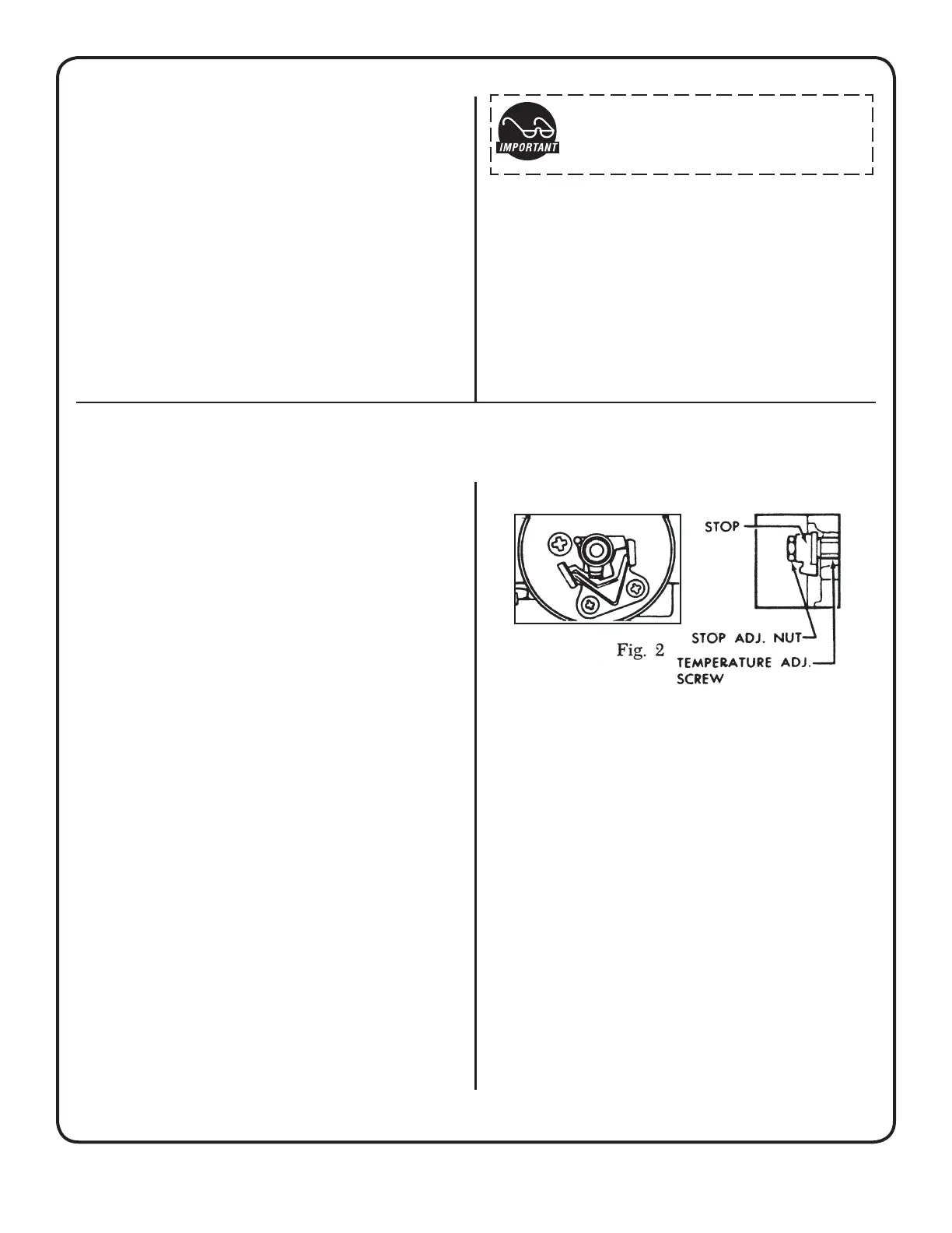
7. Turn the stop slowly until the control snaps off.
Holding the stop to prevent rotation, carefully
loosen the stop adjustment nut (see gure 2).
MAIN BURNER ADJUSTMENT (GAS INPUT)
To adjust the main burner ame, turn the screw under the gas cock handle in either direction to regu-
late the ow of gas to the main burner.
8. Taking care not to move the temperature ad-
justing screw, turn the stop until it lines up with
the tick mark previously made.
9. Hold the stop in place and tighten the stop
adjustment nut.
10. Recheck the OFF temperature.
11. Replace the outside cover and thermostat
dial.
THERMOCOUPLE CONNECTION
Poor contact between the thermocouple lead
and the magnet assembly may cause the valve
to be inoperative even when the pilot is in proper
adjustment and position. If this is the problem,
clean and tighten the contact points. Remove the
thermocouple and carefully clean the parts that
make contact with the magnet assembly.
 Loading...