Chapter 2 Operational Description
MNL-0656-01 Rev A8 ECO-N/A Effective: 16 Nov 21 Page 11 of 44
CHAPTER 2 OPERATIONAL DESCRIPTION
This chapter describes how to connect and power-up the DuraNET 20-11.
CONNECTOR IDENTIFICATION
FRONT PANEL
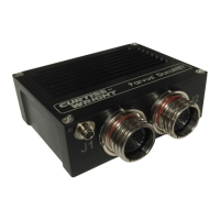
Figure 3 shows the front view of the DuraNET 20-11 and the three connectors.
Figure 3. Front View
Connector Name Description
J0 Power Input power: 5-36VDC,
J1 Gbe Gigabit Ethernet Ports 1-4
J2 GbE / Console / Zeroize Gigabit Ethernet ports 5-8, console port, Zeroize
 Loading...