Do you have a question about the Curtiss-Wright Parvus DuraNET 20-11 and is the answer not in the manual?
Overview of manual content.
Explains safety symbols used in the manual.
Details the capabilities and features of the DuraNET 20-11 switch.
Highlights key features like form factor, management, and rugged design.
Describes available product configurations and part numbers.
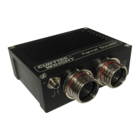
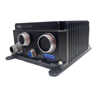
Illustrates the DuraNET 20-11 interfaces and connections.
Explains the available management interfaces (CLI and Web GUI).
Identifies and describes the unit's connectors on the front panel.
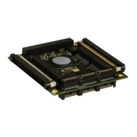
Shows the bottom view and mounting screw locations.
Lists recommended equipment for lab testing.
Details the components of the breakout cable set for testing.
Step-by-step guide to powering on and configuring the switch.
Instructions for mounting the unit vertically or horizontally.
Guidance on selecting a suitable mounting location for heat dissipation.
Details on attaching the baseplate using mounting holes and screws.
Discusses optional mounting brackets and feet for flexible installation.
Procedures for properly grounding the unit via its baseplate.
Manages switch features via serial connection, useful for initial setup.
Manages switch features via web browser for graphical control.
Basic usage and configuration of the command line interface for the switch.
Steps to connect and configure the serial CLI on a host PC.
Provides quick start instructions for common CLI commands.
Details the login process for accessing the switch CLI.
Explains the data zeroization capability for enhanced system security.
Commands for enabling/disabling the zeroization feature via CLI.
How to trigger zeroization via hardware pin or CLI.
Categorization of CLI commands by functional groups for easier navigation.
How to use the web-based software management method for switch configuration.
Explains how to access and navigate the web GUI for switch management.
Steps to connect to the switch via the web GUI using its IP address.
Explains the function and structure of the GUI navigation pane.
Describes the Home and Logout buttons in the GUI interface.
Instructions for updating the switch firmware via the web GUI.
Lists part numbers for connectors and suggested mating connectors.
Provides pinout details for creating custom cables.
Details the pinout for the J0 power and ground connector.
Pinout for the J1 connector providing four Gigabit Ethernet ports.
Pinout for J2 connector with Ethernet, console, and zeroize functions.
Details on packet processor, management, and networking software.
Information on available Ethernet and console ports.
Capabilities like QoS, VLANs, Spanning Tree, and PTP.
Support for IPv4/IPv6 unicast static routing.
Details management protocols like Web GUI, SNMP, and CLI.
Outlines security functions like authentication and zeroization.
Covers reliability aspects, workmanship, and component quality.
Information on the optional cable set for testing.
Specifies power input requirements and consumption.
Provides physical dimensions of the unit excluding connectors.
Details physical attributes like weight, installation, and cooling.
Details operating and storage conditions, shock, vibration, and altitude.
Specifies compliance with EMI/EMC standards like MIL-STD-461F and DO-160G.
How to identify the product using P/N and serial number for support.
Contact information for the Parvus Technical Support team.
Steps for obtaining an RMA and returning the product for service.
Notes differences in connector configuration for Early Access Units.
Pinout details for EAU connectors.
Part numbers for EAU connectors and mating connectors.
Pinout for EAU J1 connector with Ethernet, power, and zeroize.
Pinout for EAU J2 connector with Ethernet and console.
| Number of Ports | 10 |
|---|---|
| Port Speed | 10/100/1000 Mbps |
| Switching Capacity | 20 Gbps |
| Forwarding Rate | 14.88 Mpps |
| Power Input | +9 to +36 VDC |
| Operating Temperature | -40°C to +71°C |
| Dimensions | 5.0" x 4.0" x 1.5" (127mm x 102mm x 38mm) |
| Weight | 1.2 lbs (0.54 kg) |
| MTBF | > 500, 000 hours, Telcordia SR-332 |
| Ethernet Ports | 10/100/1000 Mbps |