Chapter 2 Operational Description
MNL-0656-01 Rev A8 ECO-N/A Effective: 16 Nov 21 Page 13 of 44
TEST EQUIPMENT INSTALLATION
To use the DuraNET 20-11 in a lab environment, recommended equipment includes:
Appropriate cables, such as the CBL-NET-20-11-01 Breakout Cable Set
A power source applied at connector J1, 5-36VDC input, 28V nominal. A power cable is included
with the Breakout Cable Set.
A host PC with a free RS-232 port and/or an Ethernet port
BREAKOUT CABLE SET
You can test the DuraNET 20-11 interfaces and cabling prior to installation in the target system to ensure
full operational capability. Full bench-top testing can be performed by using an appropriate cable set for
this system. CBL-NET-20-11-01 is available for purchase from Parvus to support lab or bench testing
purposes. You can also create a custom set of cables made specifically for the intended target system,
vehicle, or craft; refer to Chapter 4 for connector pinouts and descriptions.
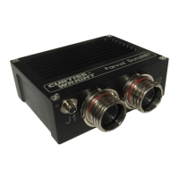
The cable set (shown in Figure 5) includes the following cables:
Cable Part # From Type
To
Type Quantity Description
CBL-2649-01 Circular Banana Plug 2 J0 (28V nominal voltage input. Red +, Black -)
CBL-2611-02 MIL Circular J1
RJ-45 4 Gigabit Ethernet ports 1-4
CBL-2612-02 MIL Circular J2
RJ-45 4 Gigabit Ethernet ports 5-8
DB-9 1 Console
Push Button 1 Zeroize
 Loading...