8. Install the Right handrail.
A. Position the right handrail in the correct position on the right side where the left handrail was
removed in step 6C.
B. Apply Threadlocker (#11) to threads inside the arm and screws removed in step 6D.
C. Secure the right handrail with the two screws and washers removed in step 6D. NOTE: When
tightened properly, frame tabs are pulled tight to the bearing.
D. Locate right linkage rod, right handrail, linkage rod cap (#17), flange spacer (#12), screw
.250-20 x .75 (#15) and washer .281 x .50 (#20). See Figure 8.
E. Secure linkage rod to handrail with linkage rod cap (#17), flange spacer (#12), BHSCS
.250-20 x .75 (#15) and washer .281 x .50 (#20) as shown in Figure 8 and 9. NOTE: The
screw (#15) m ust be tightened to a minimum of 90 inch-pounds.
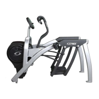
Cybex Arc Trainer 630A Owner’s Manual
Figure 10
Left Handrail
Right Handrail
Correct Position
Figure 7
#20
Right
Handrail
Setup
and Assembly
Page 5-7
F. Verify that handrails are now
installed in the correct position as
shown in Figure 10.
#12
#15
Apply
Threadlocker
Linkage Rod
Figure 9
#17
NOTE: The
BHSCS/Threadlocker
(#15) must be tightened
to a minimum of 90
inch-pounds.
#20
#17
Figure 8
#12
Linkage
Rod
#20
#17
#15
#11
#12
Linkage
Rod
Left
Handrail
NOTE: The BHSCS/
Threadlocker (#15)
must be tightened to
a minimum of 90 inch-
pounds.
#15
#11
 Loading...