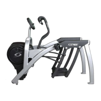
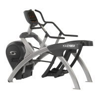
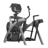
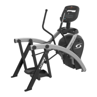
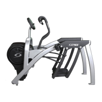
Cybex Arc Trainer 630A Owner’s Manual
NOTE: Total access arm lock assembly is only
used on total access unit.
Tools Required
• 5/32” Allen wrench
• 7/16” Open end wrench
• Drill
• 9/32” Drill bit (supplied with unit)
1. Please read instructions thoroughly
before beginning.
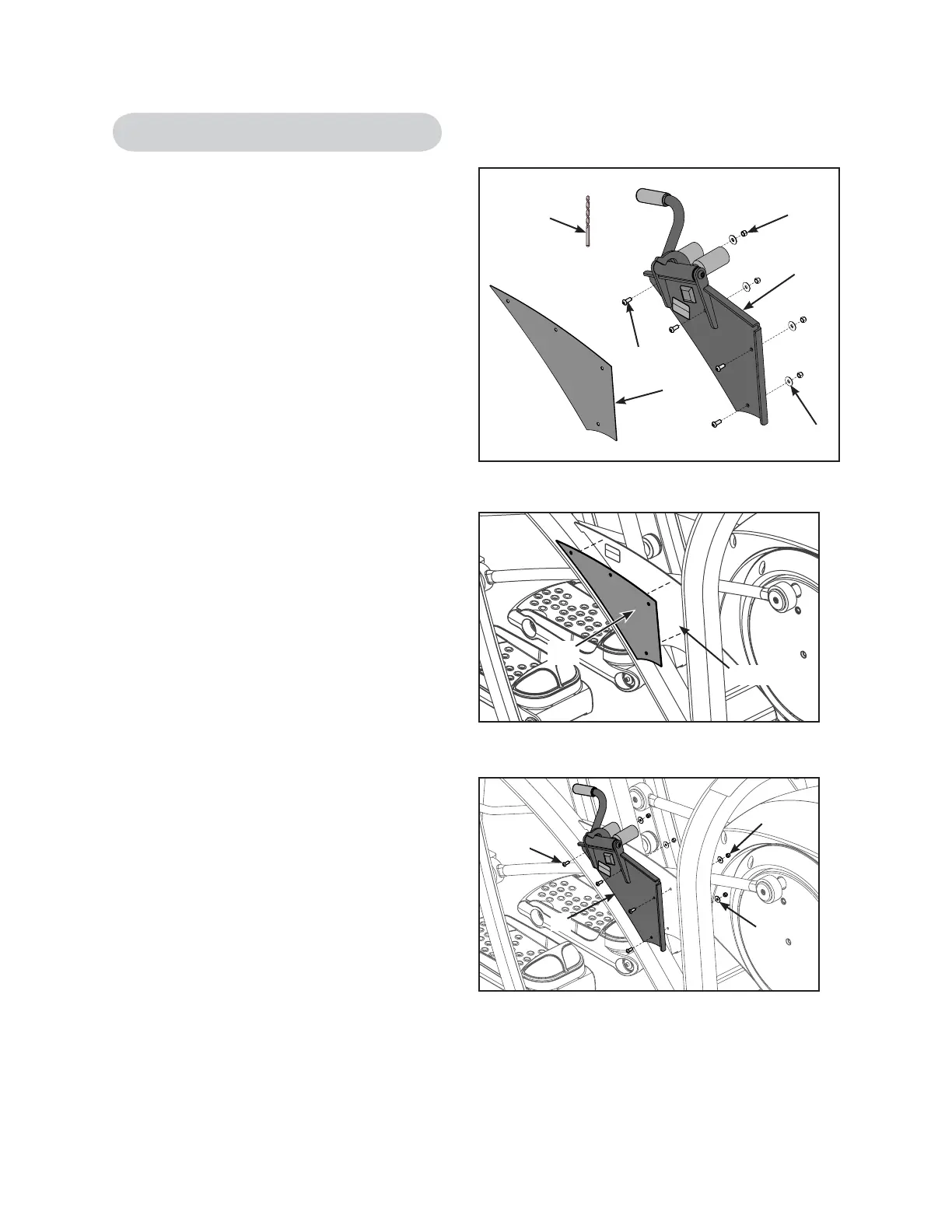
2. Verify kit contents. See Figure 1.
A. Arm lock assembly, (1), 630A-150
B. Locking assembly template, (1), 630A-345
C. BHSCS .250-20 x .625, (3), HC620414
D. Nylon locknut, (3), HN625200
E. Washer SAE .250, (3), HS307600
F. 9/32” Drill bit, (1), TE000009
3. Attach locking arm template.
A. Attach locking arm template (B) to the
outer right side plate and tape in place.
See Figure 2.
B. Using a drill and the 9/32” drill bit (F),
drill four holes as shown on the locking
arm template. See Figure 2.
C. Remove locking assembly template.
4. Attach locking arm assembly.
A. Place locking arm assembly on the side
plate. See Figure 3.
B. Using a 5/32” Allen wrench and a 7/16”
open end wrench, attach the four Button
Head Socket Cap Screws (BHSCS) (C),
washers (E) and nylon locknuts (D)
securing the locking arm assembly (A)
to the side plate. See Figure 3.
C. Test the unit to verify proper operation.
Figure 1
B
F
E
D
C
A
Side Plate
(B)
Figure 2
A
C
E
D
Figure 3
Total Access Arm Lock Assembly
Setup
and Assembly
Page 5-17
 Loading...