Cybex Arc Trainer 750A/750AT Owner’s Manual
28
Place left handle assembly in position and slide pivot pin back in place. Refer to diagram under 3.
step one above.
Secure handle assembly with the screws and washers removed in step 2 of 4. Remove left and
right handle assembly . Refer to diagram under step one above.
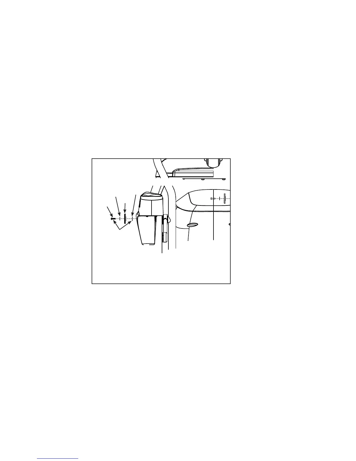
Locate left linkage rod, left handle assembly, 5. linkage rod cap 2.00 OD (#20), flange spacer (#17),
SHCS .250-20 UNC-3A SS (#19), and flat washer .281 ID x .500 OD x .062 T (#18). Refer to
diagram under step two above.
Place a drop of loctite (#16) on each 6. SHCS .250-20 UNC-3A SS (#19) and another drop inside the
shaft into which the SHCS (#19) will be tightened.
Using a 3/16” Allen wrench (#7), secure linkage rod to handle assembly with 7. linkage rod cap 2.00
OD (#20), flange spacer (#17), SHCS .250-20 UNC-3A SS (#19) and at washer, .281 ID x .500
OD x .062 T (#18).
(Both Sides–Left Side Shown)
#20
#17
#18
#19
Loctite
(#16)
NOTE: The SHCS .250-20 UNC-3A SS (#19)
must be tightened to a minimum
of 90 in/lbs.
750AT
Verify the 8. SHCS .250-20 UNC-3A SS (#19) are tightened to a minimum of 90 in/lbs.

 Loading...