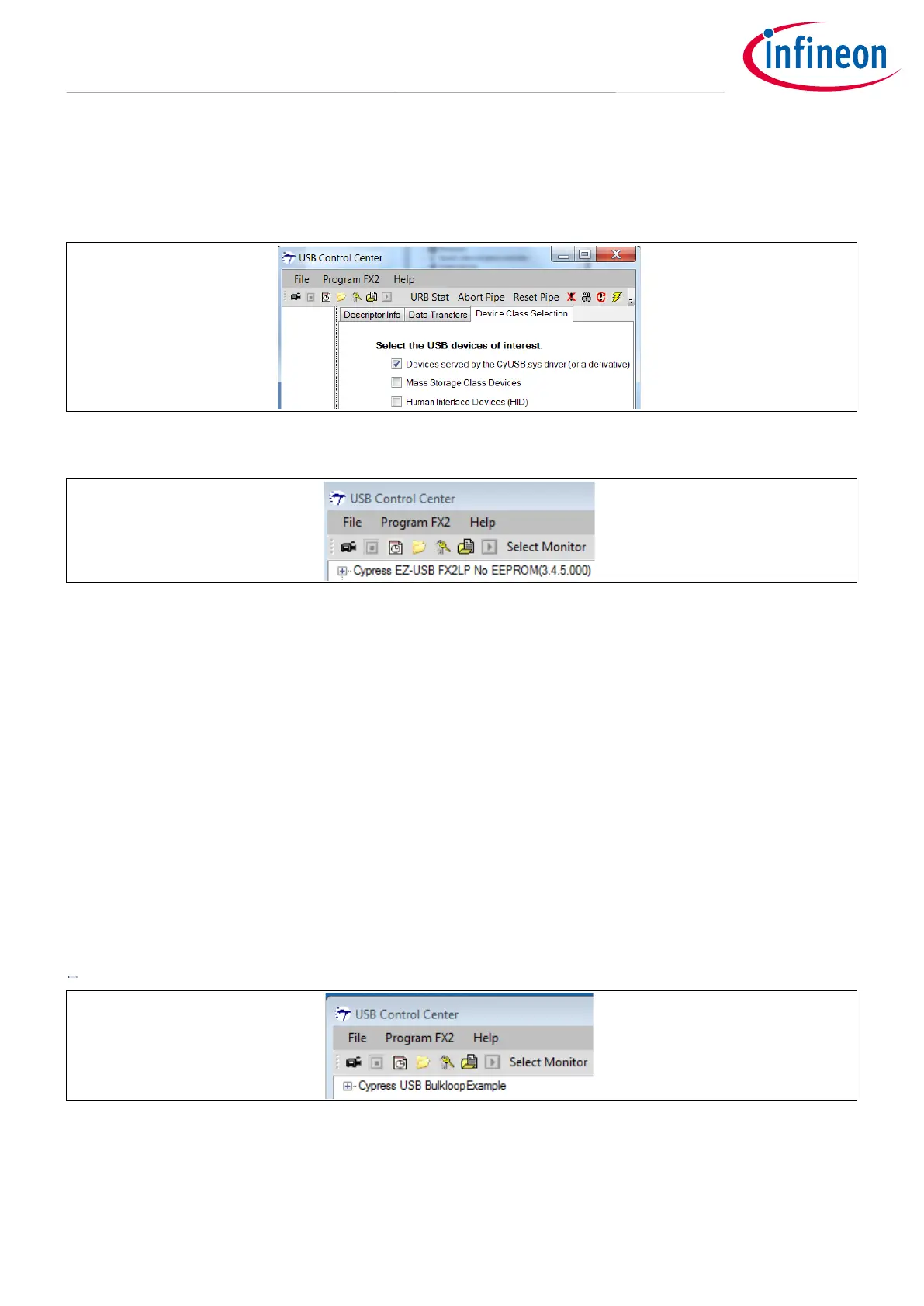
You should see the FX2LP board along with other connected USB devices listed in the left panel. To simplify this
display to show only the FX2LP board, click the Device Class Selection tab in the right panel and uncheck
everything except the Devices served by the CyUSB.sys driver (or a derivative) item.
Figure 14 USB Control Center Finds the FX2LP Board.
2. Now you are ready to load the FX2LP firmware bulkloop.hex (AN65209\FX2LP Bulkloop Firmware) on to
the FX2LP DVK. Click on the Cypress device entry to highlight it, and then select Program FX2 > RAM. Open
the FX2LP Bulkloop Firmware folder and select the bulkloop.hex file. After the code loads, the FX2LP
Development Kit disconnects itself from USB and reconnects as the device created by the loaded firmware
bulkloop.hex (Figure 15). This is Cypress ReNumeration™ in action—FX2LP has enumerated twice, first as a
code loader and then as the loaded device.
The LED D5 should blink 8 times per second for a Hi-Speed USB attachment, and once per second for a Full
Speed attachment. You can observe this by looking at the toggling frequency of the LED D5 present on the
FX2LP DVK. For Hi-Speed USB attachment, you’ll see the LED blink slowly for a second or so, and then start
blinking quickly. This is because a USB device initially attaches at Full Speed, then negotiates the Hi-Speed
connection with the host. This is one of the many firmware details handled by the Cypress USB frameworks
described in the FX2LP Firmware Development section.
The 7-segment readout present on the FX2LP DVK should light up with the number zero, indicating the number
of packets ready to be transferred back to the host—none have been received and “looped back” yet.
Figure 15 The FX2LP Board Re-appears
Note: Before you load any hex file into the FX2LP DVK, you must first press the Reset button (Error! R
eference source not found., lower left corner) by keeping the “EEPROM ENABLE” switch in “NO
EEPROM” position to reset FX2LP and thereby enable the FX2LP boot loader.

 Loading...

