1 Product Introduction DGS-1210 series Metro Ethernet Managed Switch User Manual
7
7
• Mode: By pressing the Mode button, the Port LED will switch between Link/Act and PoE modes
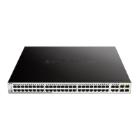
Figure 1.12 – DGS-1210-52MP/ME Front Panel
CAUTION: The MiniGBIC ports should use UL listed
Optical Transceiver product, Rated Laser Class I. 3.3Vdc.
PRÉCAUTION: Les ports Mini GBIC doivent ut
liste UL. Produit émetteur-récepteur optique, classe laser
I. 3.3Vdc.
NOTE: The power budget is 370 Watts for DGS-1210-52MP/ME.
The front panel of the DGS-1210-52MPP/ME switch consists out of the following:
• 48 10/100/1000Mbps Copper and PoE Ports
• 4 1000Mbps SFP ports
• One RJ-45 Console Port
• LEDs for Power, Console, Fan Error, PoE Max, Link/Act for port 1 ~ 52
• Mode: By pressing the Mode button, the Port LED will switch between Link/Act and PoE modes
Figure 1.13 – DGS-1210-52MPP/ME Front Panel
CAUTION: The MiniGBIC ports should use UL listed
Optical Transceiver product, Rated Laser Class I. 3.3Vdc.
PRÉCAUTION:
Les ports Mini GBIC doivent utiliser la
liste UL. Produit émetteur-récepteur optique, classe laser
I. 3.3Vdc.
NOTE: The power budget is 740 Watts for DGS-1210-52MPP/ME.
LED Indicators
The Switch supports LED indicators for Power, Console, Fan, and Link/Act for each port. The following
shows the LED indicators for the DGS-1210/ME Metro Ethernet Switch along with an explanation of each
indicator.
Figure 1.14 –LED Indicators on DGS-1210/ME SERIES
Location LED Indicative Color Status Description
Per Device Power
Green
Power on.
Power off.
 Loading...