DGS-3100 Series Gigabit Stackable Managed Switch Hardware Installation Guide
Viewing Rear Panel
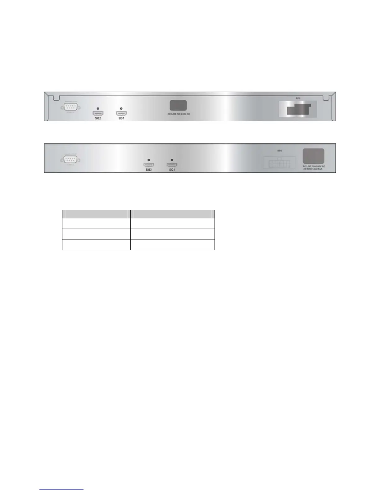
The rear panels of the switches contain an external Redundant Power Supply connector, an AC power connector, and a RS-
232 console port for setting up and managing the switch via a connection to a console terminal or PC using a terminal
emulation program.
Figure 1-4. DGS-3100 24P/48P Rear Panel View
Figure 1-5. DGS-3100-24/48/24TG Rear Panel View
• The external Redundant Power Supply connector is used to connect the DGS-3100 Series to one of the following
supported units:
DGS-3100 Series Device Supported RPS Unit
DGS-3100-24/24TG DPS-200
DGS-3100-48 DPS-500
DGS-3100-24P/48P DPS-600
An auto-switch circuit automatically switches to the external RPS once the internal power supply fails. Transition from
internal to external supply does not disturb normal operation.
• The AC power connector is a standard three-pronged connector that supports the power cord. Plug the female
connector of the provided power cord into this socket, and the male side of the cord into a power outlet. Supported
input voltages range from 100 ~ 240 VAC at 50 ~ 60 Hz.
2
 Loading...