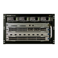
4 u D-Link DGS-6604 Modular Switch
ENGLISH
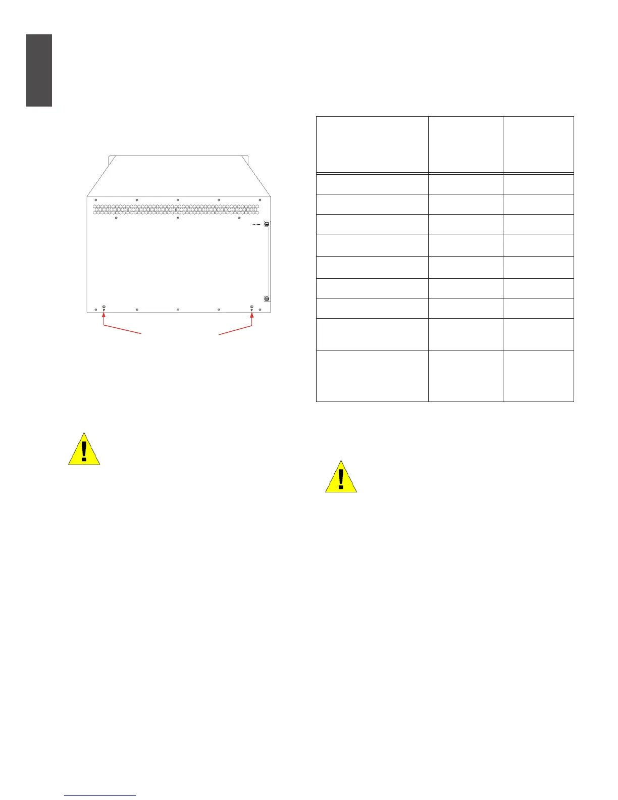
System Grounding Requirements:
Proper grounding will help to ensure stable
and reliable operation of the DGS-6604. Be
sure to verify that the grounding conditions
at the installation meet the grounding
requirements and ground all devices
appropriately.
Ground Connection
Power Requirements
The power consumption and heat dissipation
gures of the various DGS-6604 components are
listed in the table below:
DGS-6600 Series
Module
Maximum
Power
Consumption
(W)
Heat
Dissipation
(BTU/Hour)
DGS-6600-CM 54 184
DGS-6600-48T 110 375
DGS-6600-48S 119 405
DGS-6600-48TS 114 390
DGS-6600-48P 873 2979
DGS-6600-8XG 200 684
DGS-6600-24SC2XS 106 360
DGS-6600-FAN
Fan Tray
43 144
DGS-6600-PWR
AC Power Supply
854
(@110VAC
or 220 VAC)
2913
(@110VAC
or 220 VAC)
Figure 2. Grounding of the DGS-6604
Note:
All grounding conductors should
be connected before the AC power
is applied to the DGS-6604 in-
stalled AC power supplies.
The DGS-6604 with AC power
supplies must be grounded with
a minimum of 0.823 mm2 (or
18AWG) of conductive ground-
ing cable. This cable is connected
between the Equipment Room
Ground and the DGS-6604 Chas-
sis Ground Terminal.
Table 2. Card Power Requirements
Note:
The DGS-6604 provides either
1+1, 2+1, or 3+1 redundant AC
power supplies. D-Link
recommends to use multiple
power supplies for the equipment
to ensure continuous and stable
operation. Redundant power
supplies help to prevent
unexpected power failures.
Redundant power supplies must
be identical.
 Loading...