D-Link DGS-6604 Modular Switch u 7
ENGLISH
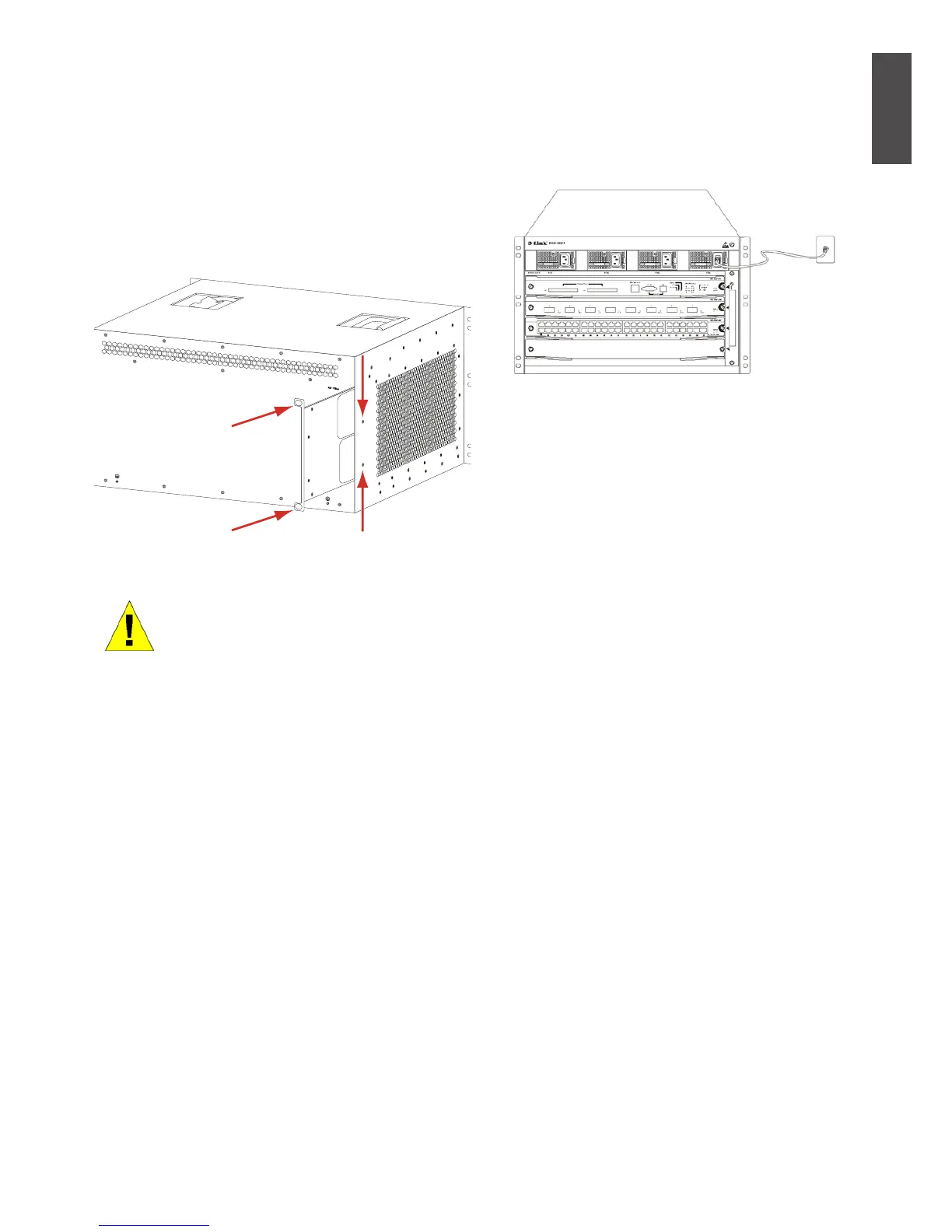
Installing the Air Filter of the DGS-6604
On the back of the chassis on the edge of the
right-side is a vertical slot where the air lter
can be tted. Slide in a cleaned or new air lter
into the slot as per the following diagram. Then
screw the two thumb/Phillips screws (see the
diagram arrows) to secure the air lter into the
chassis. With the air lter installed screw-in two
screws on the side of the chassis as indicted
by the red arrows in the diagram.
Figure 7. Installing the Air Filter
Air lter installation is recommend-
ed as the last step of the chassis
installation.
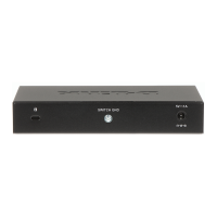
Connecting the AC Power Supply to the
Power Module
Use the related AC power cable to connect to
the AC power module panel, as indicated in
the following diagram:
Figure 8. Connecting AC to the Power Module
AC Power Supply Connection Precaution
• Verify that the provided external power
sup ply matches the power module installed
in the Switch before connecting the power
supply.
• Use a power cable with a standard 3-pin
connector to make the power connection.
• Ensure that the connected power cables
have good contacts.
• Once the power cable is plugged-in at both
power outlet and the power supply, the
power supply will immediately start.
Simple AC Power Connection Steps
1. Insert the power cable’s plug into the
power module.
2. Secure the power cable to the cable clip on
the right.
3. Connect the other end of the power cable
into the corresponding socket or connector.
 Loading...