ENGLISH
GB
70
entrance at a depth of at least 30cm below the water level and
must be watertight along its whole length, as far as the entrance
to the electropump.
7KHVXFWLRQDQGGHOLYHU\SLSHVPXVWEH¿WWHGVRWKDWWKH\GRQRW
exert any mechanical pressure on the pump.
2.1.2 Loading Operation
Installation above head and below head
Installation “above head” (par. 2.1.1): access the technical compart-
ment and, with the aid of the accessory tool (Fig.3_point 5) or with a
VFUHZGULYHUUHPRYHWKH¿OOLQJFDS)LJBSRLQW)LOOWKHV\VWHPZLWK
clean water through the loading door, taking care to let the air out. If the
non-return valve on the suction pipe (recommended in paragraph 2.1.1)
has been placed close to the system entry door, the quantity of water
ZLWKZKLFKWR¿OOWKHV\VWHPVKRXOGEHOLWUHV,WLVUHFRPPHQGHGWR¿W
the non-return valve at the end of the suction pipe (foot valve) so as to
EHDEOHWR¿OOLWTXLFNO\WRRGXULQJWKHORDGLQJRSHUDWLRQ,QWKLVFDVHWKH
quantity of water necessary for the loading operation will depend on the
length of the suction pipe (2.2 litres + …).
Installation “below head” (par. 2.1.1): if there are no check valves
between the water deposit and the system (or if they are open), it loads
automatically as soon as it is allowed to let out the trapped air. So slack-
HQLQJWKH¿OOLQJFDS)LJBSRLQWHQRXJKWRYHQWWKHWUDSSHGDLUDOORZV
the system to load completely. You must survey the operation and close
the loading door as soon as the water comes out (however it is recom-
PHQGHGWR¿WDFKHFNYDOYHLQWKHVHFWLRQRIWKHVXFWLRQSLSHDQGWRXVH
it to control the loading operation with the cap open). Alternatively, in the
case where the suction pipe is intercepted by a closed valve, the loading
operation may be carried out in a similar way to the one described for
installation over head.
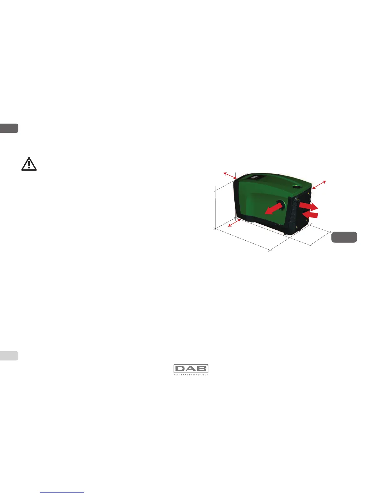
2.2 - +RUL]RQWDO&RQ¿JXUDWLRQ
Remove the 4 support feet from the bottom tray of the packaging and
screw them fully into their brass seats on face E. Put the system in place,
taking into account the dimensions in Fig.10.
7KHGLVWDQFHRIDWOHDVWPPEHWZHHQ)DFH%RIWKHV\VWHP
and an obstruction is recommended so as to be able to carry out
maintenance on the non-return valve without disconnecting the
system.
7KHGLVWDQFHRIDWOHDVWPPEHWZHHQ)DFH$RIWKHV\VWHP
and an obstruction is recommended so as to be able to remove
the door and gain access to the technical compartment.
7KHGLVWDQFHRIDWOHDVWPPEHWZHHQ)DFH'RIWKHV\VWHP
and an obstruction is obligatory to let out the power supply cable.
,IWKHVXUIDFHLVQRWÀDWXQVFUHZWKHIRRWWKDWLVQRWWRXFKLQJDQGDGMXVW
its height until it contacts the surface so as to ensure the stability of the
system. The system must in fact be placed in a safe and stable position,
ensuring that its axis is vertical: it must not be in an inclined position.
2.2.1 Hydraulic connections
Make the connection at input to the system through the mouth on Face C
marked “IN” in Fig.10 (suction connection). Then remove the respective cap
10 mm
200 mm
270 mm
OUT 1
OUT 2
IN
565 mm
370 mm
265 mm
Figure 10
 Loading...