ENGLISH
GB
67
Failure to respect the above equation may lead to malfunctions
of the system or to premature breakage of the diaphragm inside
the maintenance of the set air pressure value, proceed to check
disconnect the pump from the power supply and open the utility
nearest to the pump, keeping it open until it no longer gives any
is typically the component subject to wear for items of this type.
7KHV\VWHPKDVDEXLOWLQPXOWLLPSHOOHUFHQWULIXJDOHOHFWURSXPS6SHFL¿
driven by a water-cooled three-phase electric motor. Cooling of the motor
PD[LPXPÀRZUDWH OPLQ
(set up)
(set up)
(set up)
(set up)
(set up)
(set up)
0
5
10
15
20
25
30
35
40
45
50
55
60
65
0 10 20 30 40 50 60 70 80 9 0 100 110 120 130
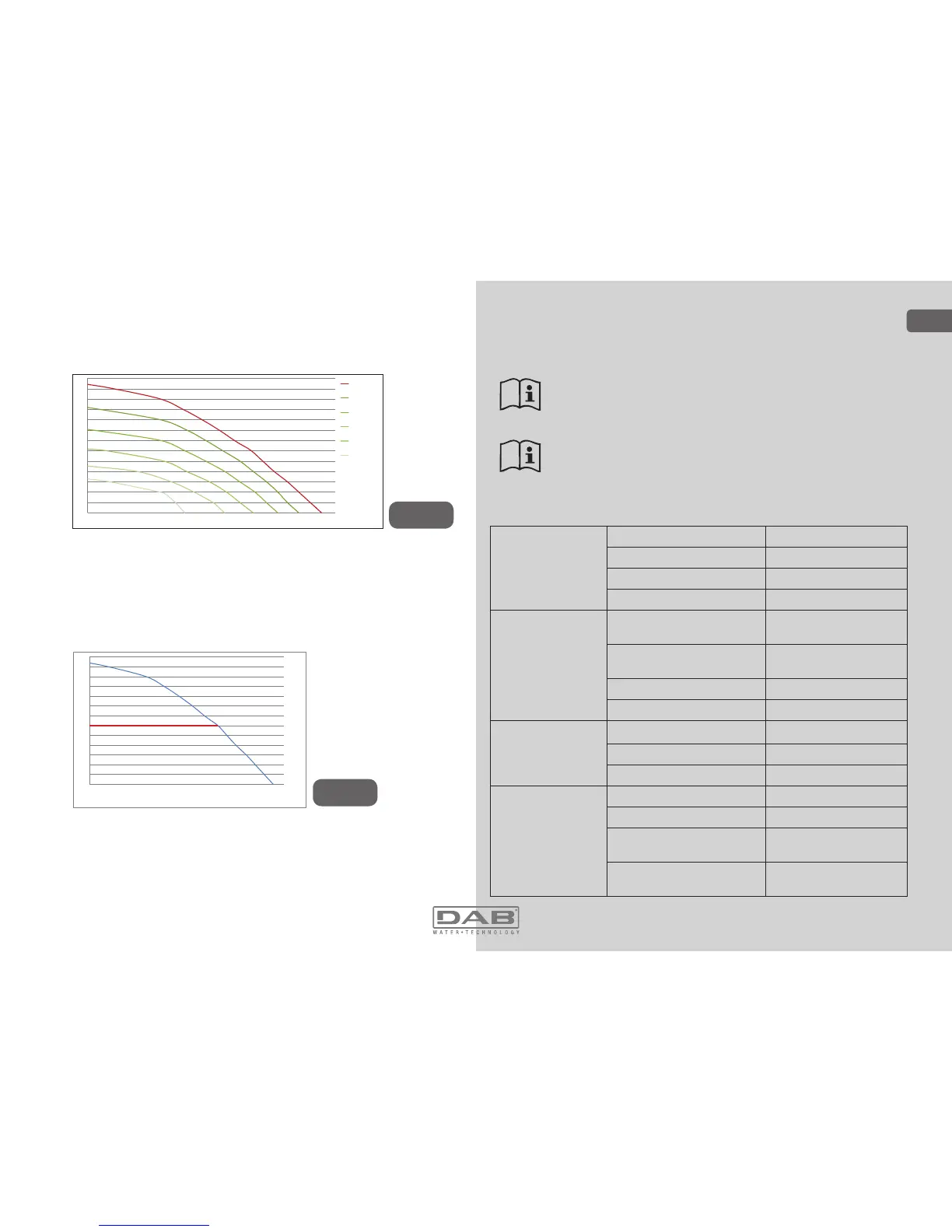
Figure 6
The same graph in Fig.6 shows in green other characteristic curves
corresponding to reduced rotation speeds of the same electropump.
By
automatically modulating the rotation speed of the electropump, the in-
verter allows it to move its operation from one of the characteristic curves
to another, maintaining the constant set pressure value (SP). Practically,
the resulting curve of the system controlled by the inverter becomes the
one shown in Fig.7 (considering a default SP value = 3.0 bar).
This means that, with SP = 3.0 bar, the system is able to ensure the
FRQVWDQWVHWSUHVVXUHWRXWLOLWLHVWKDWUHTXLUHÀRZUDWHVEHWZHHQDQG
OLWUHVPLQXWH)RUKLJKHUÀRZUDWHVWKHV\VWHPZRUNVDFFRUGLQJWRWKH
characteristic curve of the electropump at maximum rotation speed. For
ÀRZUDWHVORZHUWKDQOLWUHVPLQXWHDVZHOODVHQVXULQJFRQVWDQWSUHV-
Figure 7
0
5
10
15
20
25
30
35
40
45
50
55
60
65
0 10 20 30 4 0 50 60 70 80 90 100 110 120 1 30
sure, the system reduces the absorbed power and therefore the energy
consumption.
The above performances are to be considered measured at
DPELHQWWHPSHUDWXUHDQGZDWHUDWDERXW&GXULQJWKH¿UVW
10 minutes of motor operation, with water level at suction at a
depth of no more than 1 metre
As the suction depth increases, the performance of the electro-
pump decreases.
1.4 Technical characteristics
ELECTRIC POWER
SUPPLY
Voltage 1 x 220/240 ~ VAC
Frequency 50/60 Hz
Maximum current 11 A
Maximum power 1550 W
CONSTRUCTION
CHARACTERISTICS
Overall dimensions 565x265x352 mm without
feet
Empty weight (excluding
packaging)
24,8 kg
Protection class IP x4
Motor insulation class F
HYDRAULIC
PERFORMANCE
Maximum head 65 m
0D[LPXPÀRZUDWH 120 l/min
Priming <5min at 8m
WORKING
CONDITIONS
Maximum working pressure 8 bar
Liquid temperature max 40 °C
Environment temperature
max
50 °C
Storage environment
temperature
-10÷60 °C
 Loading...