Polaris 1000 User’s Manual
Page 15
2.6 Meter Installation
(1) Attach the dedicated CTs to the CT terminal with their appropriate phases.
(2) Connect the phase A voltage terminal of the Polaris to the corresponding
power source with an intermediate fuse.
(3) Connect the voltage terminals of the Polaris to their corresponding phase
voltages. (* Use 10 to 18 AWG, 600V wire for the voltage terminals.)
(4) Assemble the CTs onto the corresponding conductors being measured
making sure that the direction and orientation of the CTs with wiring are
consistent. With solid core CTs, the wire must be threaded through the CT,
which would necessitate disconnecting the wire from the load. With split core
CTs and clamp type CTs, the CT can be opened and clipped or clamped onto
the conductor without the need to disconnect the wiring to the load.
2.7 CT Installation
The Polaris can only make use of the dedicated CTs provided by DAE. There are
two types of dedicated CTs as shown in the following descriptions.
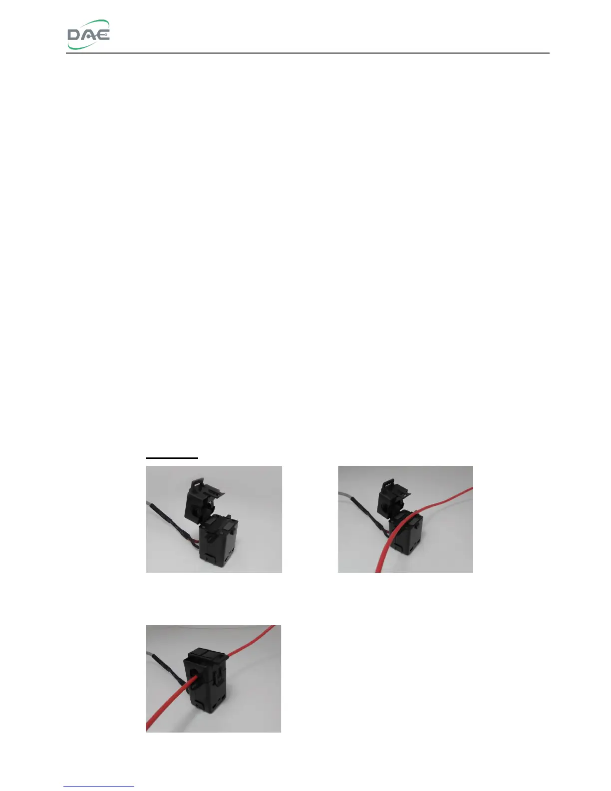
(1) Split-core CT installation
Load side
Step 1. Open the split-core CT Step 2. Lay the load wire inside the
opening
Step 3. Snap close the split-core CT
 Loading...