Installation Guide 6
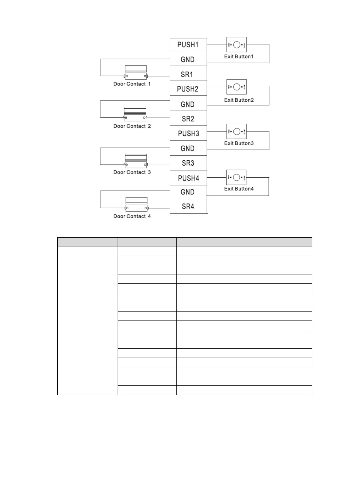
Figure 2-5
Table 2-1
Exit button+ door
contact
Shared by exit button of door 1 and door contact
input of door 1
Door contact input of door 1
Shared by exit button of door 2 and door contact
input of door 2
Door contact input of door 2
Shared by exit button of door 3 and door contact
input of door 3
Door contact input of door 3
Shared by exit button of door 4 and door contact
input of door 4
Door contact input of door 4
2.3.3 Wiring Description of Lock
Support 4 groups of lock control outputs; serial numbers after the terminals represent
corresponding doors. Please choose a proper connection mode according to lock type, as
 Loading...