8
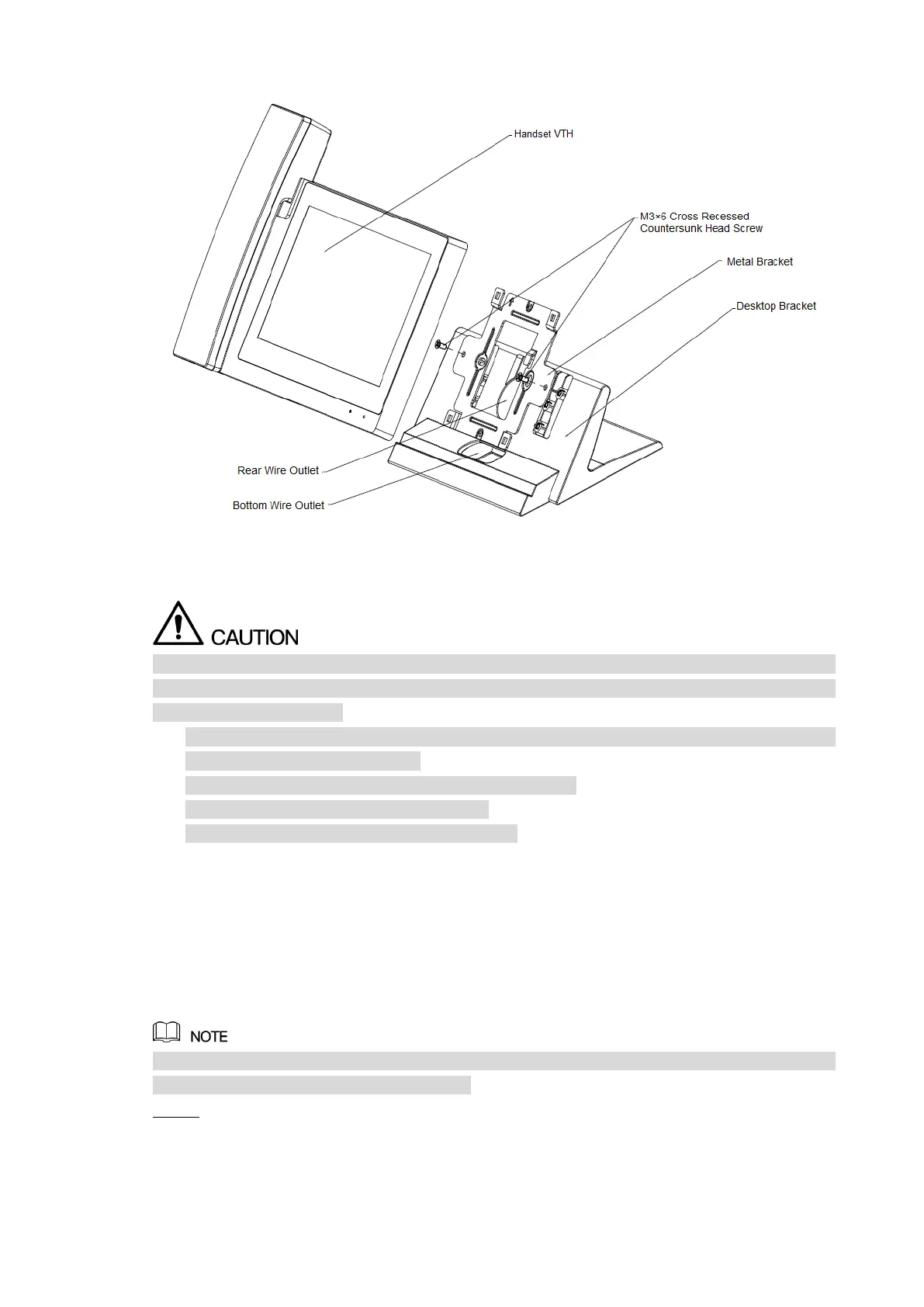
Desktop installation with bracket Figure 2-3
Debugging 2.2
Carry out debugging to ensure that the device can realize basic network access, call and
monitoring functions after installation. Before debugging, please check whether the following
work has been completed.
Check whether there is short circuit or open circuit. Power on the device only after the
circuit is confirmed to be normal.
IP and no. of every VTO and VTH have been planned.
Ensure deployment position of SIP server.
Please scan QR code on the cover for details.
Set VTO info and VTH info at WEB interface of every VTO, set VTH info, network info and VTO
info on every VTH, and thus realize video intercom function.
2.2.1 VTO Settings
VTO interfaces of different models might be different, and the actual interface shall prevail.
For the first time, please initialize and modify login password.
Please ensure that default IP addresses of PC and VTO are in the same network segment.
Default IP address of VTO is 192.168.1.110.
Power on the device, and enter default IP address of VTO at the address bar of PC Step 1
browser. The system displays “Device Init” interface, as shown in Figure 2-4.
 Loading...