3
Table 2-2 Rear panel description
No. Name Description
1 Anti-tampering switch
When the VTO is removed from the wall forcibly, an alarm will
be triggered and the alarm information will be sent to
management center.
2 Ports
Connect to power supply, electric control lock, solenoid lock
and exit button.
3 Ethernet port Connect to network cables.
4 Cascade connection port Connect to other modules.
Ports description
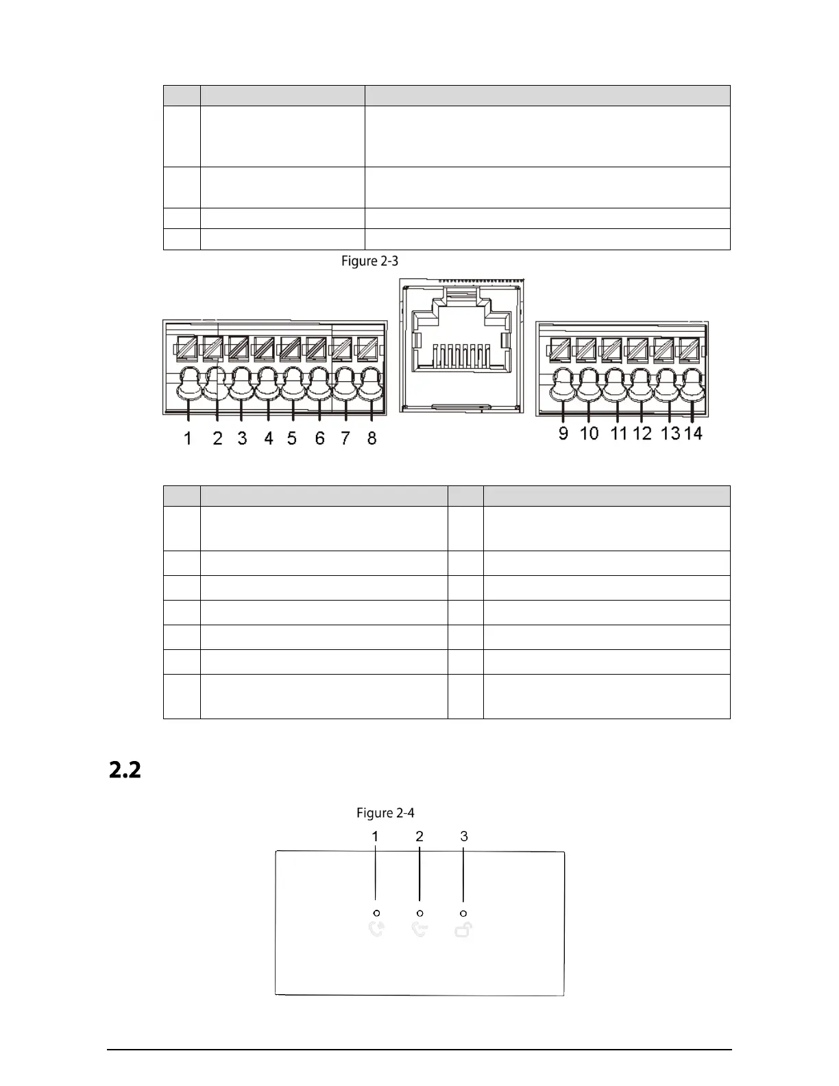
Table 2-3 Port description
No. Description No.
Description
1 GND 8
EOC1 (2wires –(GND) for a 2-wire camera
module)
2 +12V_OUT 9 DOOR_BUTTON
3 RS-485_B 10 DOOR_FEEDBACK
4 RS-485_A 11 GND
5 ALARM_NO 12 DOOR_NC
6 ALARM_COM 13 DOOR_COM
7
EOC2 (2wires +(48V) for a 2-wire camera
module)
14 DOOR_NO
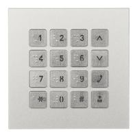
Indicator Module
Front panel
 Loading...