Structure 3
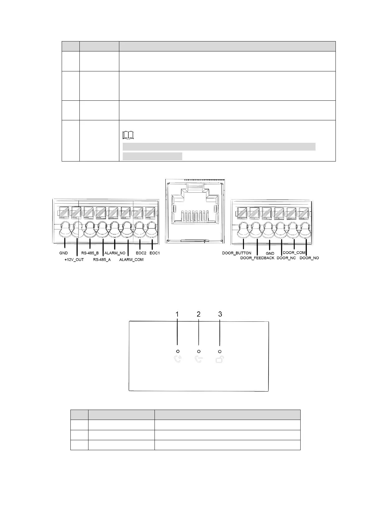
Table 2-2 Camera module (rear panel) description
When VTO is detached from the wall forcibly, alarm sound will be made
and alarm information will be sent to management center.
Provide power port, lock port, door sensor feedback port and exit button
port to connect power supply, electric control lock, solenoid lock and exit
button. See Figure 2-3.
Connected to network cables.
Connect other modules.
In case of cascade connection of multiple modules, modules need
cascade connection.
User ports Figure 2-3
Indicator Light Module 2.2
Indicator light module (front panel) Figure 2-4
Table 2-3 Indicator light module description
Indicate the call status.
Indicate the talk status.
Indicate the unlock status.
 Loading...