7 | Piping installation
Installer reference guide
39
2(A)MXM40+50 + 2(A)MXF40+50
R32 Split series
4P600463-2C – 2020.08
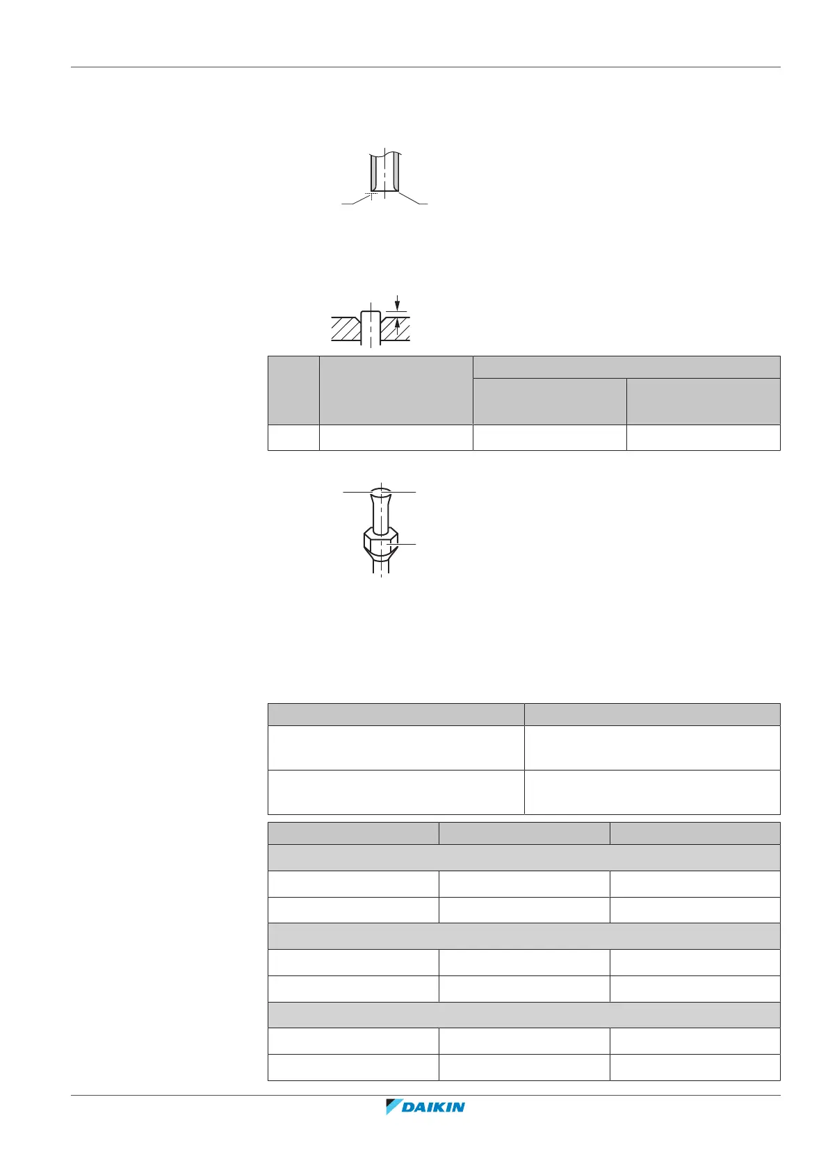
1 Cut the pipe end with a pipe cutter.
2 Remove burrs with the cut surface facing down so that the chips do NOT enter
the pipe.
a Cut exactly at right angles.
b Remove burrs.
3 Remove the flare nut from the stop valve and put the flare nut on the pipe.
4 Flare the pipe. Set exactly at the position as shown in the following figure.
Flare tool for R32
(clutch type)
Conventional flare tool
Clutch type
(Ridgid-type)
Wing nut type
(Imperial-type)
A 0~0.5mm 1.0~1.5mm 1.5~2.0mm
5 Check that the flaring is properly made.
a Flare’s inner surface MUST be flawless.
b The pipe end MUST be evenly flared in a perfect circle.
c Make sure the flare nut is fitted.
7.2.6 Connections between outdoor and indoor unit using reducers
Total indoor unit capacity class that can be connected to this outdoor unit:
Outdoor unit Total indoor unit capacity class
2MXM40, 2AMXM40, 2AMXF40,
2MXF40
≤6.0kW
2MXM50, 2AMXM50, 2AMXF50,
2MXF50
≤8.5kW
Port Class Reducer
2MXM40, 2AMXM40
A 15, 20, 25, 35 —
B 15, 20, 25, 35 —
2AMXF40
A 25, 35 —
B 25, 35 —
2MXF40
A 20, 25, 35 —
B 20, 25, 35 —
 Loading...