9 | Electrical installation
Installer reference guide
52
2(A)MXM40+50 + 2(A)MXF40+50
R32 Split series
4P600463-2C – 2020.08
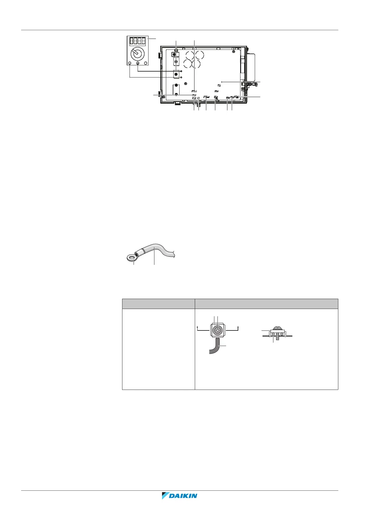
a DB1 diode bridge
b S90 thermistor lead wire
c LED A
d S40 thermal overload relay lead wire
e S20 (white) room A electronic expansion valve coil
f S21 (red) room B electronic expansion valve coil
g S80 (white) 4-way valve lead wire connector
h S70 fan motor lead wire
i S99 heating lock
j S91 (red) liquid thermistor lead wire
k S92 (white)gas thermistor lead wire
l Multimeter (DC voltage range)
9.1.2 Guidelines when connecting the electrical wiring
Keep the following in mind:
▪ If stranded conductor wires are used, install a round crimp-style terminal on the
end of the wire. Place the round crimp-style terminal on the wire up to the
covered part and fasten the terminal with the appropriate tool.
a Stranded conductor wire
b Round crimp-style terminal
▪ Use the following methods for installing wires:
Wire type Installation method
Single-core wire
a Curled single-core wire
b Screw
c Flat washer
 Loading...