49
©2014DaikinNorthAmerica,LLC
4. Acoolingairflowof1007 CFMcanbe
attainedbysettingthecoolingspeedto“C”.
5. Coolingspeed“C“canbe setforyour
furnaceon“SwitchBank:S3”locatedonthe
furnaceboard.
6. “CoolingSpeedTapC”isinpositions1and
2ofdipswitchS3.
7. Position1issetto“OFF.”
8. Position2issetto“ON.”
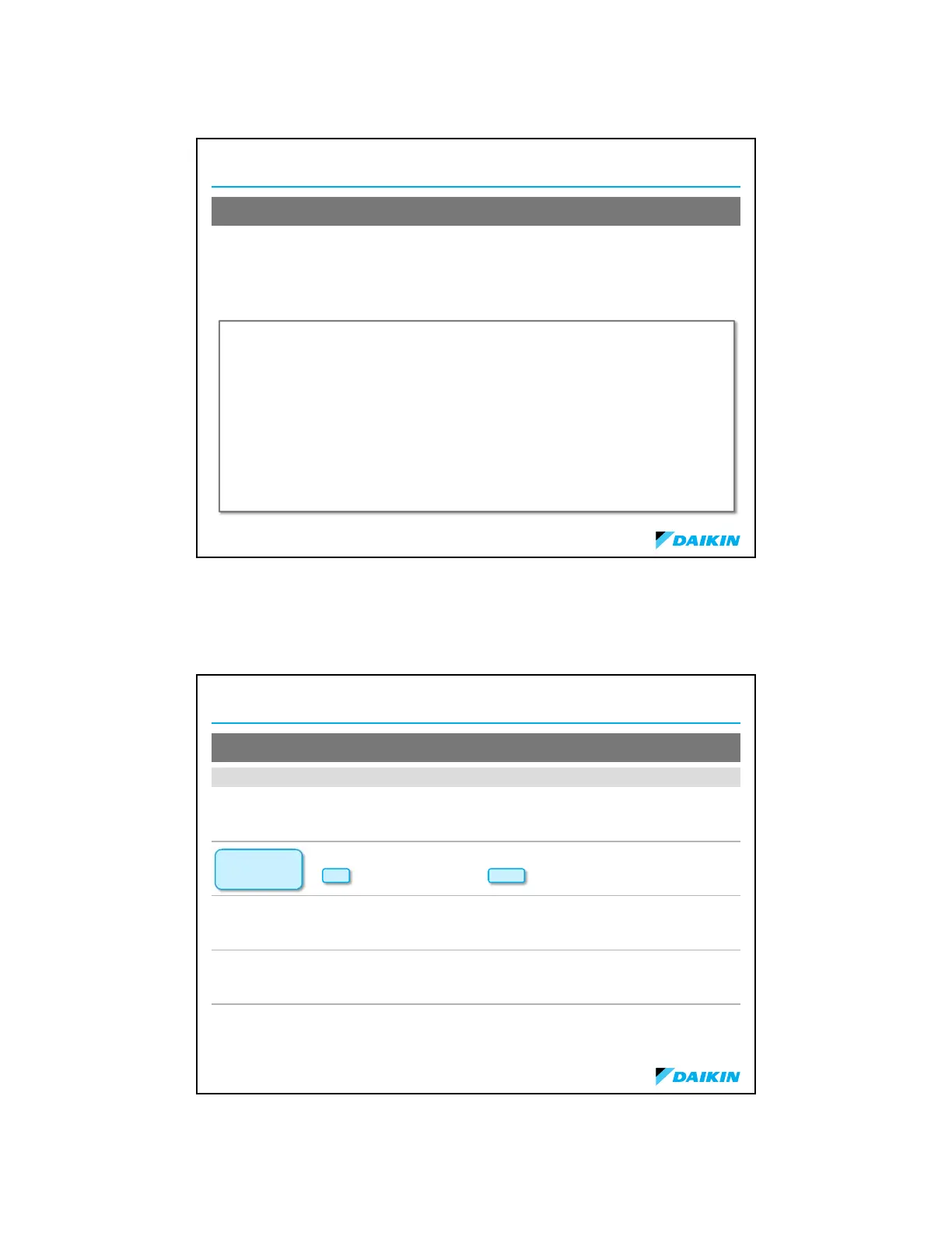
BlowerSpeedAdjust
1. A*DM96VC0603B*model
furnacehasbeeninstalledwitha
2.5tonairconditioningsystem.
2. Theairflowneededis1000
CFM.
3. Lookingatthecoolingspeed
chart/airflowtableinyour
furnacemanualfora
*DM96VC0603B*,findtheair
flowclosestto1000CFM.
Example3
Knowingthefurnacemodel,locatethehighstagecoolingairflowchartsinthe
furnace“specificationsheet”applicabletoyourmodel.Lookupthecoolingair
flowdeterminedinexample3above,andfindtherequiredcoolingspeedand
adjustthesetting.
©2014DaikinNorthAmerica,LLC
BlowerSpeedAdjust
Model Tap LowStageCool HighStageCool LowStageHeat HighStageHeat
DM96VC0403BN
A
B
C
D
403
527
675
803
596
796
974
1192
422
471
521
574
494
553
601
676
DM96VC0603BN
A
B
C
D
398
557
696
810
599
817
1007
1212
667
740
808
881
953
1059
1158
1260
DM96VC0803BN
A
B
C
D
403
540
705
819
629
806
1023
1230
855
923
1033
1063
1202
1316
1389
1396
DM96VC0804CN
A
B
C
D
513
660
791
913
789
967
1182
1375
867
939
1016
1077
1228
1337
1430
1516
DM96VC1005CN
A
B
C
D
564
784
982
1259
820
1133
1464
1736
1256
1292
1316
1358
1818
1870
1910
1957
AirflowTablefromManualIOD‐2008(2StageHeat/VariableSpeedECM)
 Loading...