3 Product description
Installation and maintenance instructions
11
Daikin Altherma EHS(X/H)(B)-D
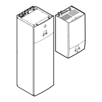
Heat pump (indoor unit) with integrated heat accumulator
008.1444099_01 – 11/2018 – EN
Item Designation Item Designation
1 Solar - inflow 25 Type plate
2 Cold water connection 26 Protective cover
3 Domestic hot water 27 Solar - return flow
4 Heating inflow 28 Biv - inflow
5 Heating return flow 29 Biv - return flow
6 Circulation pump 30 Plate heat exchanger
7 Pressure relief valve 31 Connection for refrigerant
fluid line
7a Non-return valve (ac-
cessory)
32 Connection for refrigerant
gas line
8 Automatic vent valve 33 Status display
9 Storage tank (polypropyl-
ene double walled jacket
with PUR hard foam heat
insulation)
34 Ball valve (heating cir-
cuit)
10 Filling and draining con-
nection or solar return
flow connection
35 Combined filling and
draining valve (heating
circuit)
11 Mount for solar controller
or handle
37
t
DHW1
,
t
DHW2
Storage tank temperature
sensor
12 Heat exchanger (stain-
less steel) for domestic
hot water heating
38 Connection for dia-
phragm expansion vessel
13 Heat exchanger (stain-
less steel) for storage
tank charging or heating
support
39 Control system housing
14 Biv heat exchanger
(stainless steel) for char-
ging with external heat
generator (e.g. pressur-
ised solar system)
3UVB
1
3-way switch valve (in-
ternal heat generator cir-
cuit)
15 Connection for optional
electrical backup heater
EKBUxx
3UV
DHW
3-way switch valve (hot
water/heating)
16 Solar - inflow layering
pipe
DS Pressure sensor
17 Fill level indicator (tank
water)
FLS FlowSensor
18 Optional: electric backup
heater (EKBUxx)
t
R
Return flow temperature
sensor
19 Submersible sensor
sleeve for storage tank
temperature sensor t
DHW1
and t
DHW2
t
V
Inflow temperature
sensor
20 Pressure-free storage
tank water
t
V, BH
Backup heater inflow
temperature sensor
21 Solar zone RoCon
+ B1
Controller control panel
22 Hot water zone EKS-
RPS4
Optional: Solar control
and pump unit
23 Safety overflow connec-
tion
MAG Diaphragm expansion
vessel
24 Mount for handle
Tab.3-1 Legend for Fig. 3-1 to Fig. 3-4
3.2 Function of the 3-way switch
valves
Fig.3-5 3-way switch valve function

 Loading...

