•Altherma
TM
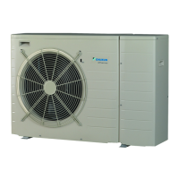
• Outdoor units
63
• Outdoor units • ERHQ011-016AAW1
6 Wiring diagram
6 - 1 Wiring diagram
2
6
ERHQ011-016AAW1
2TW57916-1C
A1P Printed circuit board
A2P Printed circuit board (INV)
A3P Printed circuit board (Noise filter)
BS1∼BS4 Push button switch
C1∼C4 Capacitor
DS1 DIP switch
E1HC Crankcase heater
E1H Bottomplate heater
F1UF1U Fuse (31.5A 500V)
F2U Fuse (31.5A 500V)
F3U Fuse (T 6.3A / 250V)
F4U Fuse (T 6.3A / 250V)
F5U Fuse (T 6.3A / 250V)
F6U Fuse (T 6.3A / 250V)
F7U Fuse (T 5.0A / 250V)
F8U, F9U Fuse (F 1.0A / 250V)
HAP (A1P) Pilot lamp (Service monitor-green)
HAP (A2P) Pilot lamp (Service monitor-green)
H1P∼7P (A1P) Pilot lamp (Service monitor-orange)
K1M-K2M Magnetic contactor
K1R (A1P) Magnetic relay (Y1S)
K1R (A2P) Magnetic relay
K2R (A1P) Magnetic relay (Y2S)
K3R (A1P) Magnetic relay (E1HC)
L1R∼L3R Reactor
L4R Reactor (For outdoor fan motor)
M1C Motor (Compressor)
M1F Motor (Fan) (upper)
M2F Motor (Fan) (lower)
PS Switching power supply
R1∼R4 Resistor
R1T Thermistor (Air)
R2T Thermistor (Discharge)
R3T Thermistor (Suction)
R4T Thermistor (Heat exchanger)
R5T Thermistor (Heat exchanger middle)
R6T Thermistor (liquid)
R7T Thermistor (Fin)
S1NPH Pressure sensor
S1PH Pressure switch (high)
V1R∼V2R Power module
V3R Diode module
X1M Terminal strip
Y1E Electronic expansion valve
Y1S Solenoid valve (4 way valve)
Y3S Solenoid valve
Z1C∼Z9C Noise filter
Z1F∼Z4F Noise filter
Q1DI Earth leakage protector
Optional connector
X6A Connector
X77A Connector
X1Y Connector
Notes:
1 This wiring diagram only applies to the outdoor unit
2 L:Live, N: Neutral, g: Field wiring
3 D : Terminal strip F : Connector GM: Connection
R : Protective earth (screw)
: Connector
p : Noiseless earth G : Terminal
4 Refer to the option manual, for connecting wiring to x6A and X77A
5 Refer to the ’wiring diagram sticker’ (on the back of front plate) on how to
use BS1-BS4 and DS1 switch.
6 Do not operate the unit by short-circuiting protection device S1PH
7 Colors: BLK: black, RED: red, BLU: blue, WHT: white, YLW: yellow, ORG:
orange, BRN: brown, GRN: green
8 Confirm the method of setting the selector switches (DS1) by service
manual.
Factory setting of all switches: ’Off’
9
: Option : Wiring dependent on model
arrow A
Indoor
Compressor
terminal position
Power supply
3N∼
400V
50Hz
El. comp. Assy Front
Reactor box A
arrow B
Reactor terminal position
Only for *RHQ01*AAW18
EKBPHT16Y
Only for
*RHQ01*AAW1
Outdoor
Note: 4
 Loading...