IM 1240-4 • INTELLIGENT EQUIPMENT 14 www.DaikinApplied.com
Connection of EMM to Split-Core CT’s
(Not on Gateway-on-the-Go, IE Express, or
WMC kits)
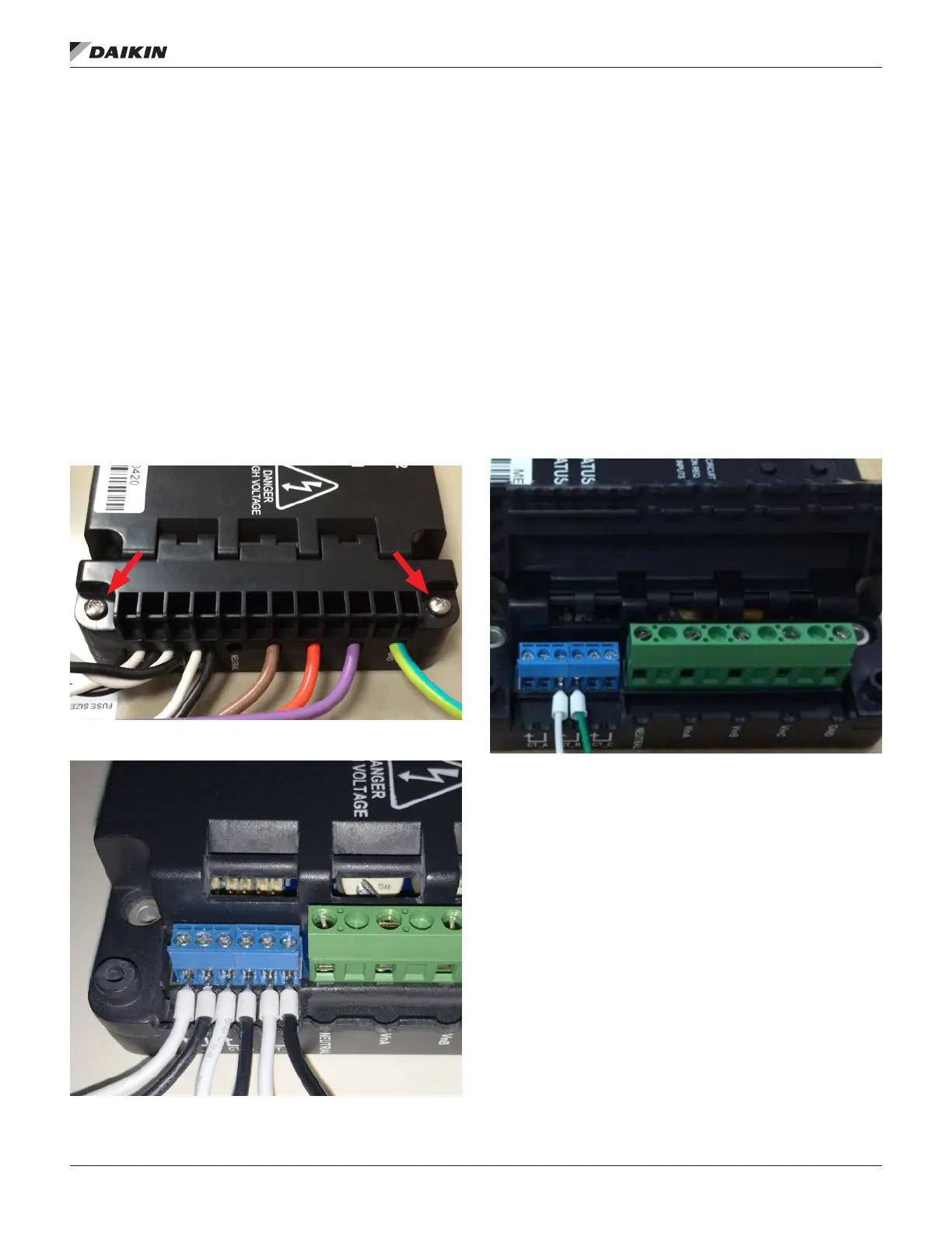
The high voltage side of the EMM has a hinged cover, which
must be opened. First, remove the two installation screws
(Figure 24), then ip the cover open. The EMM uses an open
style hinge, so it may be easier to completely remove the
hinged door while installing conductors.
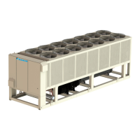
The CT’s have built-in output conductors, which must be
connected to the EMM. Each black conductor must be
connected to an EMM terminal labeled, “CT”, while each white
conductor must be connected to the corresponding terminal
labeled, “A”, “B”, or “C”. The two conductors from each CT
must be connected to the same terminal set, i.e. – “CT” and
“A”, “CT” and “B”, or “CT” and “C”. For each CT, the white wire
must go to terminal labeled ‘CT’ and the black wire must go to
the associated lettered terminal (Figure 25).
Figure 24: Hinged Cover Screw Locations
Figure 25: Connection of EMM to CT’s
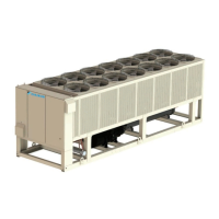
Connection of EMM to Rogowski Coil CT’s
(Not on Gateway-on-the-Go, IE Express, or
WMC kits)
Chillers with larger incoming power bundles will require the use
of a exible CT called a Rogowski coil. The connection of the
exible CT is similar to that of a split-core CT. The Rogowski coil
CT’s have built-in output conductors, which must be connected
to the EMM. Insert the white conductor from the Rogowski coil
CT on Line 1 into the CT_A+ terminal, and the green conductor
from the Rogowski coil CT on Line 1 into the CT_A- terminal.
Next, insert the white conductor from the Rogowski coil CT on
Line 2 into the CT_B+ terminal, and the green conductor from
the Rogowski coil CT on Line 2 into the CT_B- terminal. Finally,
insert the white conductor from the Rogowski coil CT on Line
3 into the CT_C+ terminal, and the green conductor from the
Rogowski coil CT on Line 3 into the CT_C- terminal. Figure 26
provides an example of these connections.
Figure 26: Connection of EMM to Rogowski Coil CT’s