www.DaikinApplied.com 21 IM 1240-4 • INTELLIGENT EQUIPMENT
Rooftop Installation Instructions
Installing Mounting Brackets
Prior to installing the mounting brackets, power must be
removed from the unit. Power must be removed at the breaker
panel serving the unit, and proper lockout/tagout procedures
should be followed for the duration of the install. After removing
unit power at the breaker panel, the installer must verify the
absence of power at the unit using a multimeter. Only if power
has been veried absent, should the technician begin the install.
The retrot kit is shipped with two mounting brackets: one
bracket contains the M2M Gateway and power supply, the
other contains the EMM and fuse block (with 5A Fuses pre-
installed). The EMM and Fuse block are not included for
on Gateway-on-the-Go or IE Express. In a retrot scenario,
these brackets must be installed inside the unit control panel.
For MPS and DPS units, the brackets are designed for
installation inside of the main unit control panel, mounted to the
top of the unit controller section (see Figure 41 for preferred
locations) using the provided sheet metal screws (5/16" head).
The bracket containing the M2M Gateway should be mounted
to the left of the enclosure, and the bracket containing the
EMM should be mounted to the right side of the enclosure
(Figure 41). For RPS, RPR, RDT, RFS, RDS and RAH units,
the M2M bracket is designed for installation on the inside of the
lower, left internal enclosure door (Figure 42), and the EMM
bracket is designed for installation on the inside of the lower,
right internal enclosure door (Figure 43).
Care must be taken to ensure that the mounting brackets are
not installed in such a way as to interfere with closing of the
control panel door, or to cover any panel knock-outs. It may be
useful to mark the screw holes of the bracket, and drill small
pilot holes, before screwing the brackets rmly to the top of the
control enclosure.
In some enclosure congurations, particularly with early DPS
and MPS units, the control enclosure layout and dimensions
may not allow for the desired mounting locations. In these
situations, the installer should use discretion in determining
suitable replacement locations within the control enclosure,
paying special attention to the following limitations:
• When routing wiring through the control enclosure,
care must be taken to maintain a minimum of 5 inches
of clearance between all cables and conductors with
300V-rated insulation or less and areas of the control
enclosure containing higher voltage components and
conductors, such as 575V.
• Avoid routing communication cables (Cat 5e, USB, etc.)
near sources of line voltage.
For reference, Figure 44 shows suitable alternative locations in
an early DPS unit with a smaller control enclosure footprint.
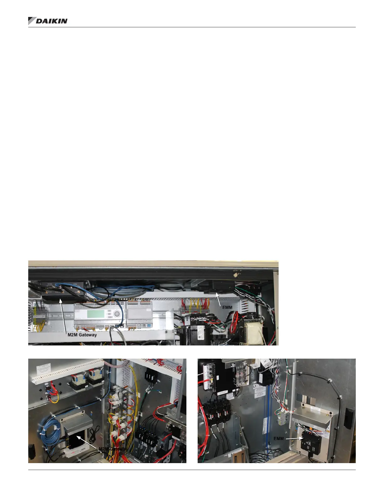
Figure 41: DPS and MPS Bracket Mounting Locations
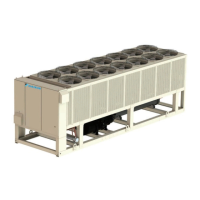
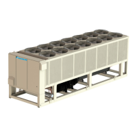
Figure 42: M2M Bracket Mounting Location - RoofPak Figure 43: EMM Bracket Mounting Location - RoofPak
M2M Gateway
EMM
M2M Gateway
EMM