www.DaikinApplied.com 9 IM 1240-4 • INTELLIGENT EQUIPMENT
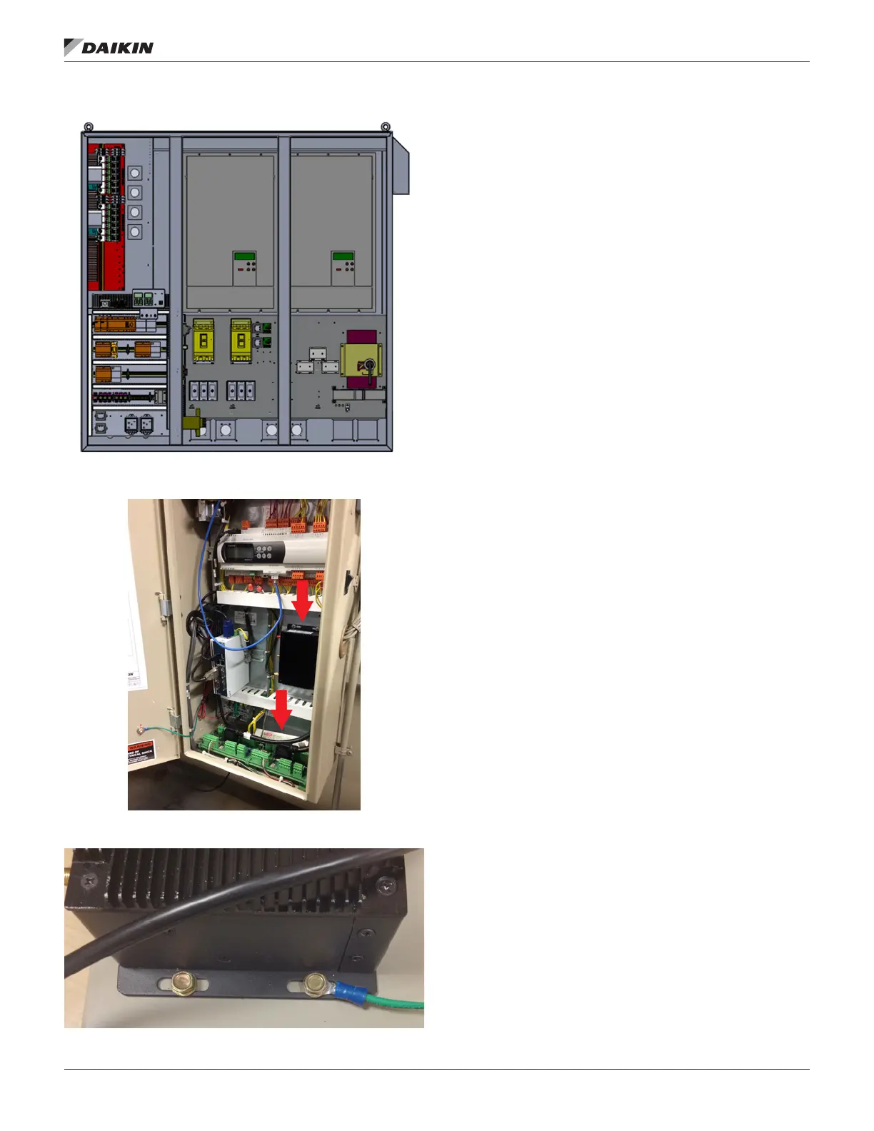
Figure 7: Component Locations – AWS Large Panel
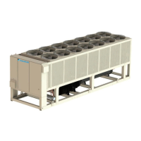
Figure 8: Component Locations – WMC Unit Control
Enclosure
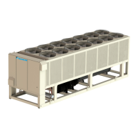
Figure 9: Installation of Grounding Ring to M2M Gateway
Installing Energy Management Module
(Not on Gateway-on-the-Go, IE Express, or
WMC kits)
Prior to installing any Intelligent Equipment components,
power must be removed from the unit. Power must be
removed at the breaker panel serving the unit, and proper
lockout/tagout procedures should be followed for the duration
of the install. After removing unit power at the breaker panel,
the installer must verify the absence of power at the unit using
a multimeter. Only if power has been veried absent, should
the technician begin the install. The retrot kit is shipped with
the EMM shipped loose. The EMM must be installed inside
the unit control panel.
The installation location will vary depending on the unit model
and size of the control enclosure (see Figure 1 through Figure
5 for correct component locations on AGZ and AWV models).
On AWS models, locate Intelligent Equipment hardware as
space allows within the control enclosure. Figure 6 and Figure
7 provide a typical layout of AWS small and large enclosures.
For AMZ chillers, eld verify component locations. Begin by
positioning the EMM on the backplane of the enclosure and
marking the screw holes. Next, drill pilot holes, through the
marks just created, using a 7/64" drill bit. Finally, attach the
EMM to the backplane using (4) of the provided #6 sheet metal
screws (5/16" head).
Installing Power Supply
Prior to installing any Intelligent Equipment components, power
must be removed from the unit. Power must be removed at
the breaker panel serving the unit, and proper lockout/tagout
procedures should be followed for the duration of the install.
After removing unit power at the breaker panel, the installer
must verify the absence of power at the unit using a multimeter.
Only if power has been veried absent, should the technician
begin the install.
The retrot kit is shipped with the power supply shipped
loose. The power supply must be installed inside the unit
control panel. The installation location will vary depending on
the unit model and size of the control enclosure (see Figure 1
through Figure 5 for correct component locations on AGZ and
AWV models). On AWS models, locate Intelligent Equipment
hardware as space allows within the control enclosure.
Figure 6 and Figure 7 provide a typical layout of AWS small
and large enclosures. On WMC chillers, only the M2M
gateway and gateway power supply are used. Locate these
components within the unit control enclosure as space allows.
Figure 8 shows a typical install for WMC. For AMZ chillers,
eld verify component locations.
Begin by positioning the power supply on the backplane of the
enclosure and marking the screw holes. Next, drill pilot holes,
through the marks just created, using a 7/64" drill bit. Finally,
attach the power supply to the backplane using (2) of the
provided #6 sheet metal screws (5/16" head).