IM 1240-4 • INTELLIGENT EQUIPMENT 16 www.DaikinApplied.com
Installing Rogowski Coil CT’s
(Not on Gateway-on-the-Go, IE Express, or
WMC kits)
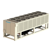
Snap the Rogowski Coil CT connected to EMM terminal
CT_A on phase L1, the Rogowski Coil CT connected to
EMM terminal CT_B on phase L2, and the Rogowski Coil CT
connected to EMM terminal CT_C on phase L3 (Figure 32).
Ensure that the “Load” indicator on the CT is oriented correctly.
The molded arrow on the snap of the CT should be pointing
toward the load.
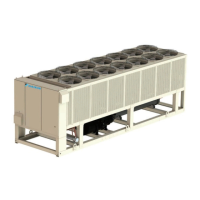
Figure 29: Rogowski Coil Power Supply Connection – AGZ
Figure 30: Rogowski Coil Power Supply Connection – AWV
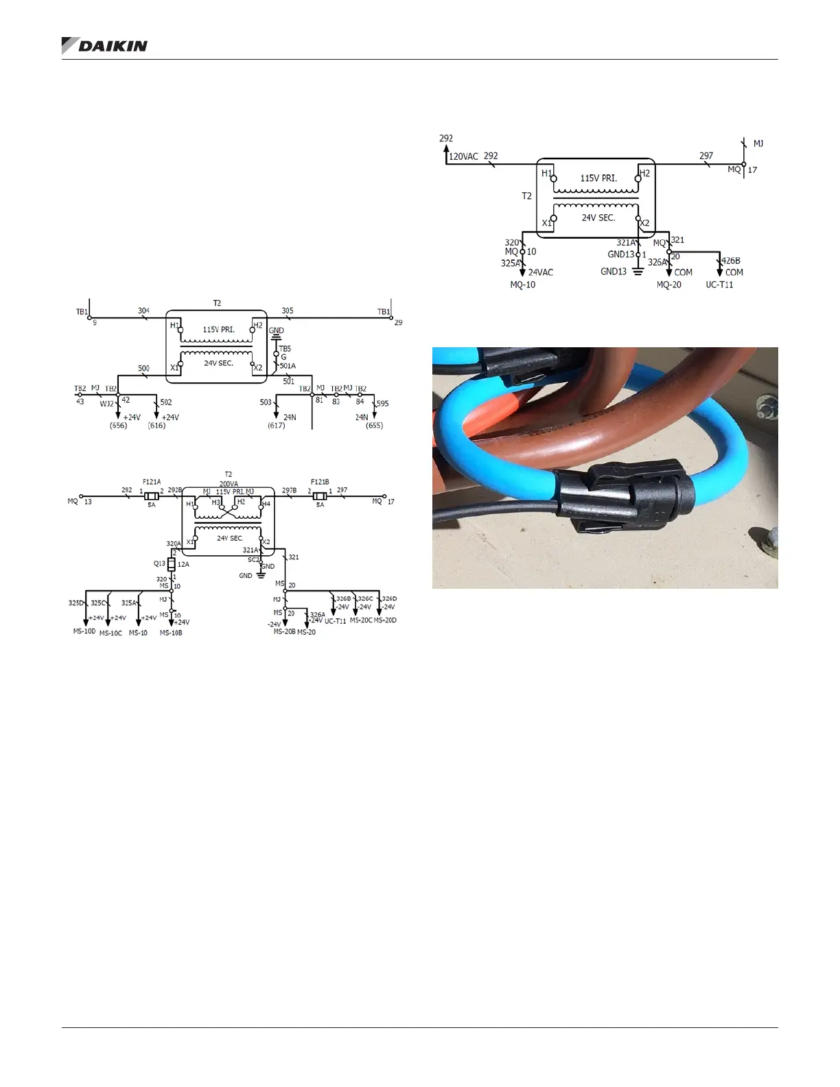
Figure 31: Rogowski Coil Power Supply Connection – AWS
Figure 32: Rogowski Coil Installation