Indoor Unit SiUS181305E
25 Printed Circuit Board Connector Wiring Diagram
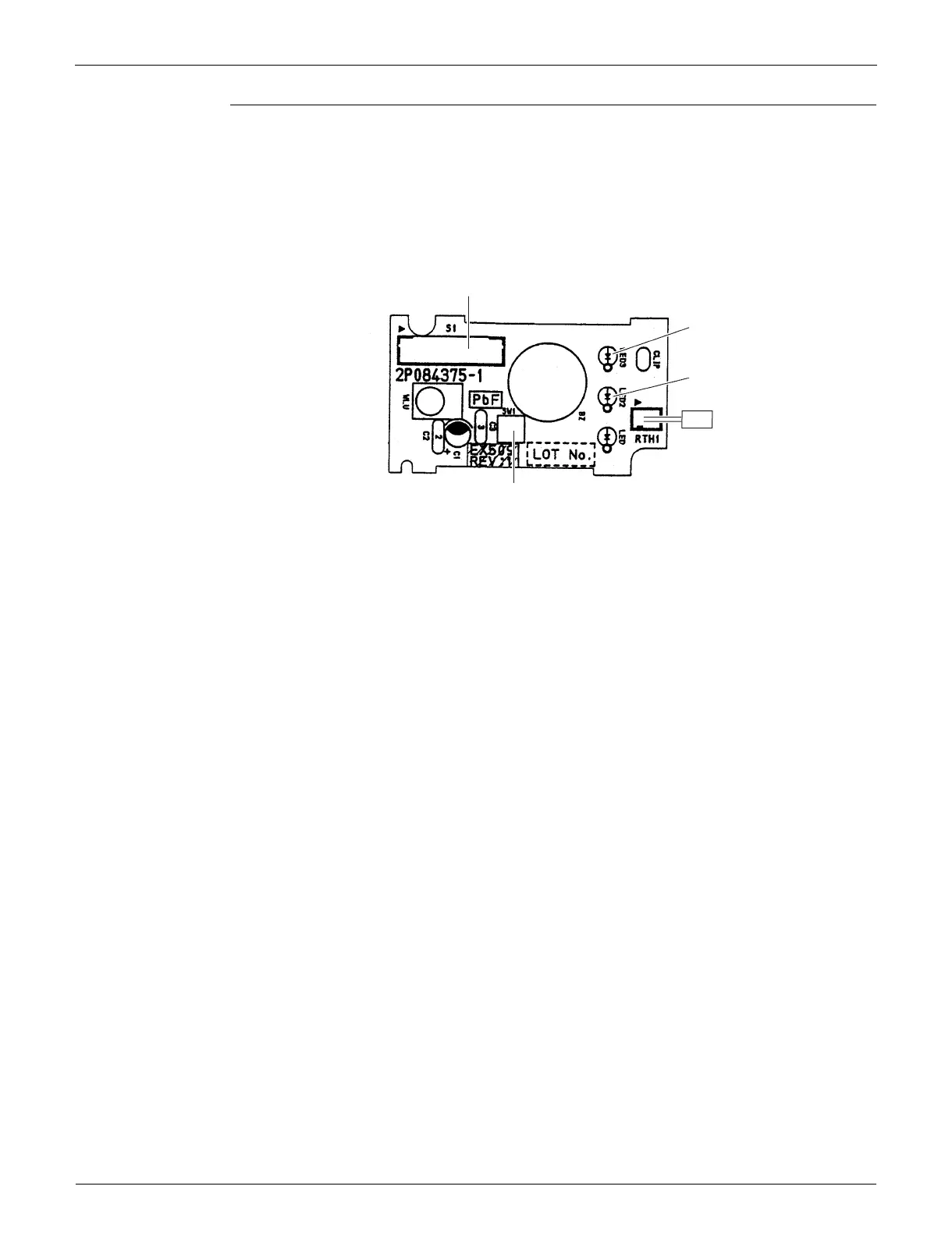
Display PCB
LED 1 does not function.
1) S1 Connector for control PCB
2) SW1 (S1W) Forced operation ON/OFF button
3) LED2 (H2P) LED for timer (yellow)
4) LED3 (H3P) LED for operation (green)
5) RTH1 (R1T) Room temperature thermistor
S1
LED3
LED2
SW1
2P084375-1
RTH1
1
 Loading...