Refrigerant Circuit SiUS181305E
31 Refrigerant Circuit
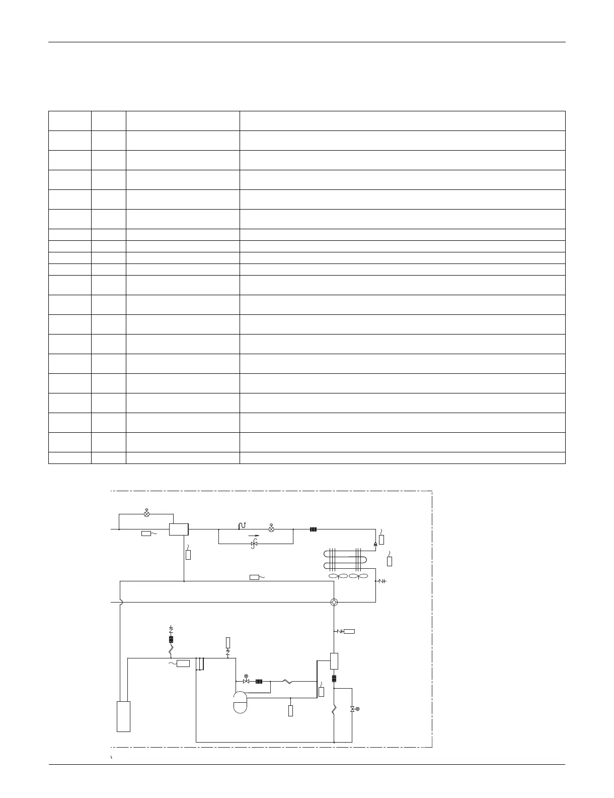
1. Refrigerant Circuit
1.1 Outdoor Unit
No. in
diagram
Symbol Name Major Function
A M1C Compressor motor
The compressor is operated on frequencies between 36 Hz and 195 Hz by using the
inverter. (31 steps)
D
M1F
M2F
Fan motor
Since the system is of air heat exchanging type, the fan is operated at 8-step rotation
speed by using the inverter.
EY1E
Electronic expansion valve
(Main)
While in heating operation, PI control is applied to keep the outlet superheated degree of
the air heat exchanger constant.
FY3E
Electronic expansion valve
(Subcooling)
PI control is applied to keep the outlet superheated degree of the subcooling heat
exchanger constant.
GY2S
Solenoid valve
(Hot gas bypass)
Prevents the low pressure from temporary falling.
H Y3S Solenoid valve (Unload circuit) Unloading operation of the compressor.
M Y1S Four-way valve Switches the operation mode between cooling and heating.
N S1NPH High pressure sensor Detects high pressure.
O S1NPL Low pressure sensor Detects low pressure.
P S1PH High pressure switch
In order to prevent the increase of high pressure when an error occurs, this switch is activated
at high pressure of 4.0 MPa (1338 ftAq) or more to stop the compressor operation.
S — Fusible plug
In order to prevent the increase of pressure when abnormal heating is caused by fire, etc., the fusible part
of the plug melts at a temperature of 70 ~ 75°C (158 ~ 167°F) to release the pressure into the atmosphere.
T—
Pressure regulating valve
(Receiver to discharge pipe)
This valve opens at a pressure of 4.0 MPa (1338 ftAq) to prevent pressure increase, thus protecting
functional parts from damage due to the increase of pressure in transportation or storage.
1R1T
Thermistor
(Outdoor temperature: Ta)
Detects outdoor temperature, correct discharge pipe temperature, etc.
2R2T
Thermistor
(Discharge pipe: Tdi)
Detects discharge pipe temperature, for temperature protection control of the compressor,
etc.
3R3T
Thermistor
(Suction pipe 1: Ts1)
Detects suction pipe temperature, keep the suction superheated degree constant in
heating operation, etc.
4R4T
Thermistor
(Outdoor heat exchanger: Tb)
Detects liquid pipe temperature of the outdoor heat exchanger, determine defrosting
operation, etc.
5R5T
Thermistor
(Suction pipe 2: Ts2)
Calculates the internal temperature of the compressor etc.
6R6T
Thermistor (Subcooling heat
exchanger gas pipe: Tsh)
Controls the subcooling electronic expansion valve.
7 R7T Thermistor (Liquid pipe: Tl) Detects refrigerant overcharge in check operation, etc.
Electronic
expansion valve
Double pipe
heat exchanger
Electronic
expansion
valve
Fusible
plug
Filter
Heat exchanger
Service port
Four-way
valve
High pressure
sensor
Solenoid valve
Solenoid
valve
Low pressure
sensor
Service port
Capillary
tube
Capillary
tube
Capillary
tube
Stop valve (with service port on field piping side
φ
7.9 mm (
φ
5/16 inch) flare connection)
Compressor
High pressure
switch
Pressure
regulating valve
Filter
Filter
Filter
er
Oil
separator
S1NPL
S1PH
S1NPH
Accumulator
(F)
(T)
(E)
(D)
(D)
(M)
(N)
(G)
(P)
(H)
(O)
(A)
(S)
(7)
(6)
(3)
(2)
(5)
(4)
(1)
 Loading...