44
PRODUCT DESIGN
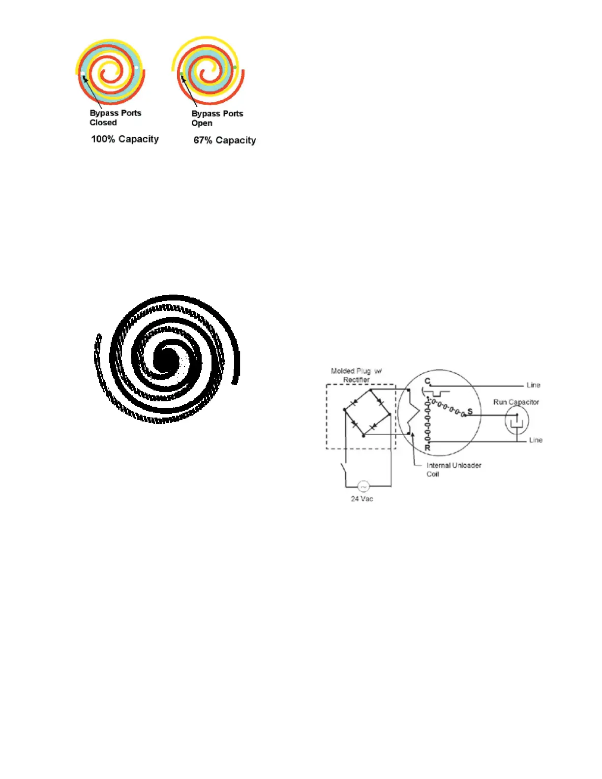
FIGURE A
A scroll is an involute spiral which, when matched with a mang
scroll form as shown, generates a series of crescent shaped gas
pockets between the two members.
During compression, one scroll remains staonary (xed scroll)
while the other form (orbing scroll) is allowed to orbit (but not
rotate) around the rst form.
As this moon occurs, the pockets between the two forms are
slowly pushed to the center of the two scrolls while simultane-
ously being reduced in volume. When the pocket reaches the
center of the scroll form, the gas, which is now at a high pres-
sure, is discharged out of a port located at the center.
During compression, several pockets are being compressed
simultaneously, resulng in a very smooth process. Both the
sucon process (outer poron of the scroll members) and the
discharge process (inner poron) are connuous.
Some design characteriscs of the Compliant Scroll compressor
are:
• Compliant Scroll compressors are more tolerant of liquid
refrigerant.
NOTE: Even though the compressor secon of a Scroll
compressor is more tolerant of liquid refrigerant, connued
oodback or ooded start condions may wash oil from the
bearing surfaces causing premature bearing failure.
• "Ultratech" Series scroll compressors use "POE" or polyo-
lester oil which is NOT compable with mineral oil based
lubricants like 3GS. "POE" oil must be used if addional oil is
required.
• Compliant scroll compressors perform “quiet” shutdowns
that allow the compressor to restart immediately without
the need for a me delay. This compressor will restart even
if the system has not equalized.
NOTE: Operang pressures and amp draws may dier from
standard reciprocang compressors. This informaon can be
found in the unit’s Technical Informaon Manual.
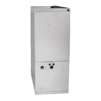
CAPACITY CONTROL - LEGACY MODELS
During the compression process, there are several pockets with-
in the scroll that are compressing gas. Modulaon is achieved
by venng a poron of the gas in the rst sucon pocket back to
the low side of the compressor thereby reducing the eecve
displacement of the compressor. See Figure A. Full capacity is
achieved by blocking these vents, increasing the displacement
to 100%. A solenoid in the compressor, controlled by an external
24-volt ac signal, moves the slider ring that covers and uncov-
ers these vents. The vent covers are arranged in such a manner
that the compressor operates somewhere around 67% capacity
when the solenoid is not energized and 100% capacity when
the solenoid is energized. The loading and unloading of the two
step scroll is done “on the y” without shung o the motor
between steps. See Figure B below. The unloaded mode default
was chosen for two reasons:
FIGURE B
1. It is expected that the majority of run hours will be in the
low capacity, unloaded mode.
2. It allows a simple two-stage thermostat to control capacity
through the second stage in both cooling and possibly heat-
ing if desired.
Unloader solenoid
A nominal 24-volt direct current coil acvates the internal
unloader solenoid. The input control circuit voltage must be 18
to 28 volt ac. The coil power requirement is 20 VA. The external
electrical connecon is made with a molded plug assembly. This
plug is connected to the Comfort Alert™ or CoreSense™ Module
(dependent upon which module you are using) which contains a
full wave recer to supply direct current to the unloader coil.