55
SERVICING
assembly that provides power to the rst heater element. When
“W1” is energized, the sequencer will close it’s contacts within
10 to 20 seconds to supply power to the rst heater element
and to the blower motor through the normally closed contacts
on the relay on the EBTDR. When the “W1” demand is removed,
the sequencer opens it contacts within 30 to 70 seconds and
removes power from the heater element and the blower motor.
The EBTDR also contains a speedup terminal to reduce the
delays during troubleshoong of the unit. When this terminal is
shorted to the common terminal, “C”, on the EBTDR board, the
delay ON me is reduced to 3 seconds and the delay OFF me is
reduced to 5 second.
Two addional terminals, M1 and M2, are on the EBTDR board.
These terminals are used to connect the unused leads from the
blower motor and have no aect on the board’s operaon.
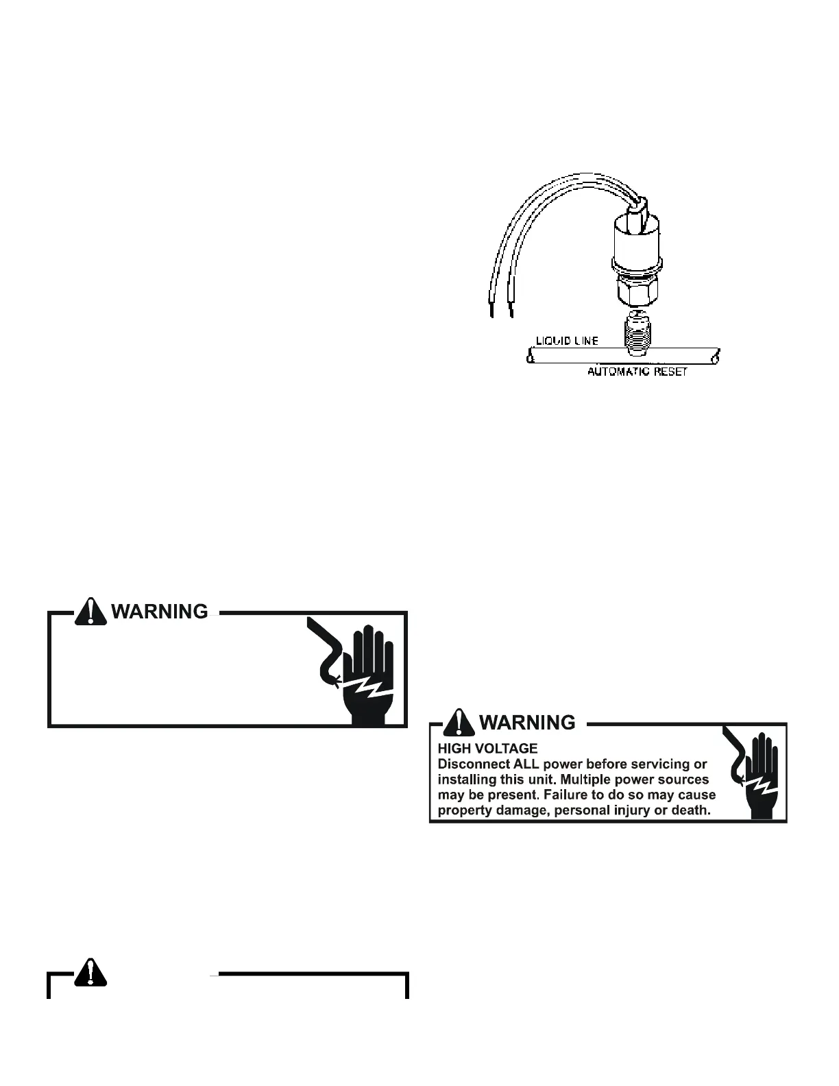
S-11 CHECKING LOSS OF CHARGE PROTECTOR
(Heat Pump Models)
The loss of charge protectors senses the pressure in the liquid
line and will open its contacts on a drop in pressure. the low
pressure control will automacally reset itself with a rise in
pressure.
The low pressure control is designed to cut-out (open) at
approximately 21 PSIG. It will automacally cut-in (close) at
approximately 50 PSIG.Test for connuity using a VOM and if not
as above, replace the control.
S-12 CHECKING HIGH PRESSURE CONTROL
HIGH VOLTAGE!
Disconnect ALL power before servicing
or installing. Multiple power sources
may be present. Failure to do so may
cause property damage, personal injury
or death.
The high pressure control capillary senses the pressure in the
compressor discharge line. If abnormally high condensing
pressures develop, the contacts of the control open, breaking
the control circuit before the compressor motor overloads. This
control is automacally reset.
1. Using an ohmmeter, check across terminals of high pressure
control, with wire removed. If not connuous, the contacts
are open.
2. Aach a gauge to the dill valve port on the base valve.
With power ON:
WARNING
Line Voltage now present.
3. Start the system and place a piece of cardboard in front of
the condenser coil, raising the condensing pressure.
4. Check pressure at which the high pressure control cuts-out.
If it cuts-out at 610 PSIG ± 10 PSIG, it is operang normally
(See causes for high head pressure in Service Problem Anal-
ysis Guide). If it cuts out below this pressure range, replace
the control.
S-13 CHECKING LOW PRESSURE CONTROL
The low pressure control senses the pressure in the sucon line
and will open its contacts on a drop in pressure. The low pres-
sure control will automacally reset itself with a rise in pressure.
The low pressure control is designed to cut-out (open) at approx-
imately 21 PSIG for heat pumps and 55 PSIG for air condioners.
It will automacally cut-in (close) at approximately 50 PSIG for
heat pumps and 95 PSIG for air condioners.
Test for connuity using a VOM and if not as above, replace the
control.
S-114A COPELAND CORESENSE™
DIAGNOSTICS - 3-WIRE MODULE
Applies to ASX /ASZ and DSX/DSZ units
The CoreSense™ module is self-contained with no required
external sensors and works with any residenal condensing unit
that has a Copeland Scroll™ compressor inside.
Once aached, CoreSense provides around-the-clock monitoring
for common electrical problems, compressor defects and broad
system faults. If a glitch is detected, an LED indicator ashes the
proper alert codes to help you quickly pinpoint the problem.
See Diagnosc Table: 3-Wire CoreSense™ Module on following
pages.)