67
SERVICING
HIGH VOLTAGE!
Disconnect ALL power before servicing
or installing. Multiple power sources
may be present. Failure to do so may
cause property damage, personal injury
or death.
1. Disassemble and remove the heang element(s).
2. Visually inspect the heater assembly for any breaks in the
wire or broken insulators.
3. Using an ohmmeter, test the element for connuity - no
reading indicates the element is open. Replace as necessary.
S-60 ELECTRIC HEATER (OPTIONAL ITEM)
Oponal electric heaters may be added, in the quanes shown
in the specicaons secon, to provide electric resistance heat-
ing. Under no condion shall more heaters than the quanty
shown be installed.
The low voltage circuit in the air handler is factory wired and
terminates at the locaon provided for the electric heater(s). A
minimum of eld wiring is required to complete the installaon.
Other components such as a Heang/Cooling Thermostat and
Outdoor Thermostats are available to complete the installaon.
The system CFM can be determined by measuring the stac
pressure external to the unit. The installaon manual supplied
with the blower coil, or the blower performance table in the
service manual, shows the CFM for the stac measured.
Alternately, the system CFM can be determined by operang
the electric heaters and indoor blower WITHOUT having the
compressor in operaon. Measure the temperature rise as close
to the blower inlet and outlet as possible.
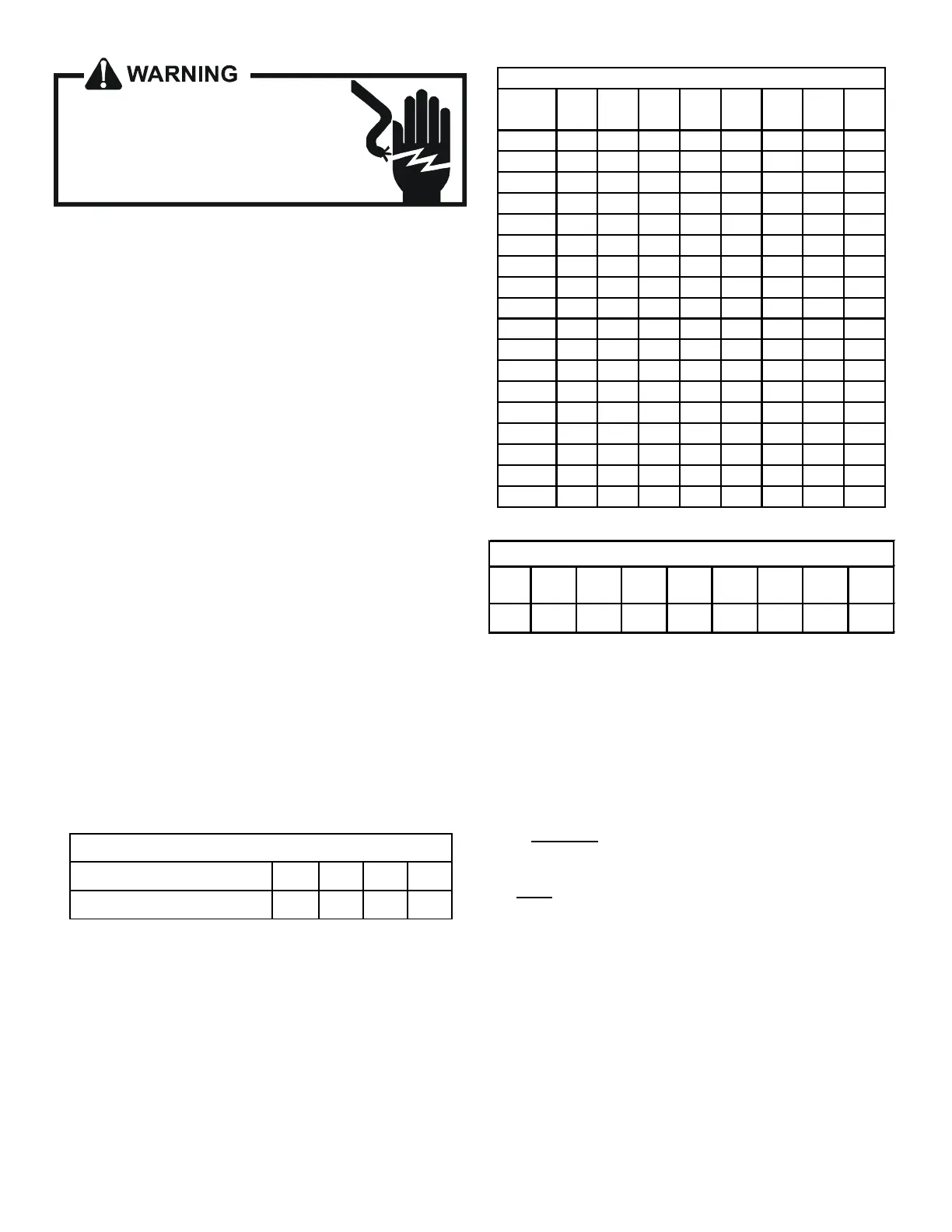
If other than a 240V power supply is used, refer to the following
BTUH CAPACITY CORRECTION FACTOR chart.
BTUH CAPACITY CORRECTION FACTOR
SUPPLY VOLTAGE
250 230 220 208
MULTIPLICATION FACTOR 1.08 .92 .84 .75
EXAMPLE: Five (5) heaters provide 24.0 KW at the rated 240V.
Our actual measured voltage is 220V, and our measured tem-
perature rise is 42°F. Find the actual CFM:
Answer: 24.0KW, 42°F Rise, 240 V = 1800 CFM from the
TEMPERATURE RISE chart on the right.
Heang output at 220 V = 24.0KW x 3.413 x .84 = 68.8 MBH.
Actual CFM = 1800 x .84 Corr. Factor = 1400 CFM.
NOTE: The temperature rise table is for sea level installaons.
The temperature rise at a parcular KW and CFM will be greater
at high altudes, while the external stac pressure at a parcu-
lar CFM will be less.
600 16 25 38 51 - - - -
700 14 22 33 43 - - - -
800 12 19 29 38 57 - - -
900 11 17 26 34 51 - - -
1000 10 15 23 30 46 - - -
1100 9 14 21 27 41 55 - -
1200 8 13 19 25 38 50 - -
1300 7 12 18 23 35 46 - -
1400 7 11 16 22 32 43 54 65
1500 6 10 15 20 30 40 50 60
1600 6 9 14 19 28 38 47 57
1700 6 9 14 18 27 36 44 53
1800 5 8 13 17 25 34 42 50
1900 5 8 12 16 24 32 40 48
2000 5 8 12 15 23 30 38 45
2100 5 7 11 14 22 29 36 43
2200 4 7 11 14 21 27 34 41
2300 4 7 10 13 20 26 33 39
TEMPERATURE RISE (°F) @ 240V
BTUH 10200 16200 20400 23800 32400 48600 66500 71600
ELECTRIC HEATER CAPACITY BTUH
FORMULAS:
Heang Output = KW x 3413 x Corr. Factor
Actual CFM = CFM (from table) x Corr. Factor
BTUH = KW x 3413
BTUH = CFM x 1.08 x Temperature Rise (T)
CFM = KW x 3413
1.08 x T
T = BTUH
CFM x 1.08
S-61A CHECKING HEATER LIMIT CONTROL(S)
Each individual heater element is protected with a limit control
device connected in series with each element to prevent over-
heang of components in case of low airow. This limit control
will open its circuit at approximately 150°F.