63
SERVICING
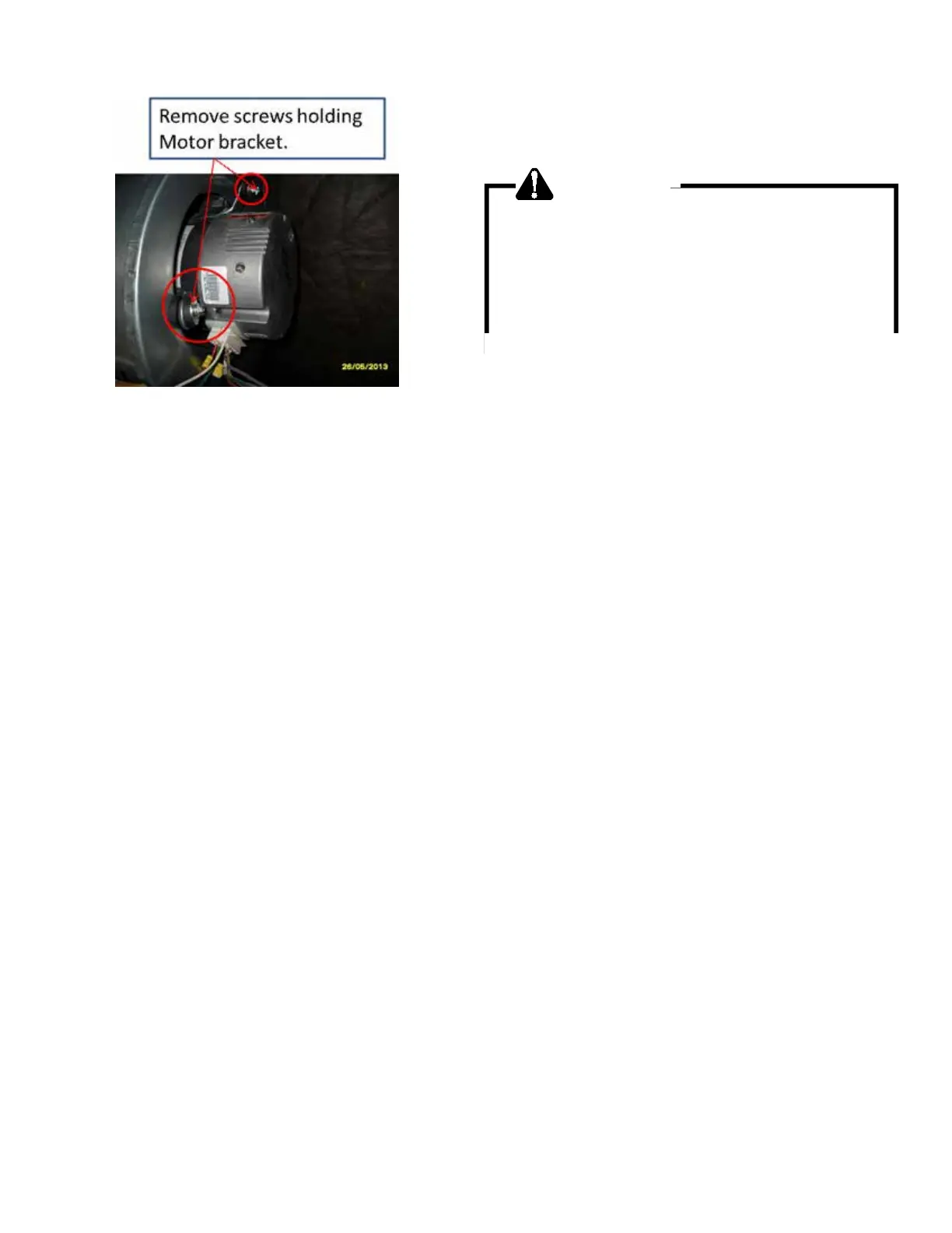
10. Remove the bolts holding the motor bracket to the
blower and slide out of blower shell.
11. Replace the motor and reinstall blower and control box.
12. Reconnect power and test operaon.
S-16C MBR/AR*F ELECTRONIC BLOWER TIME DELAY
RELAY
The MBR/AR*F contains an Electronic Blower Time Delay Relay
board, B1370735. This board provides on/o me delays for the
blower motor in cooling and heat pump heang demands when
“G” is energized.
During a cooling or heat pump heang demand, 24Vac is sup-
plied to terminal “G” of the EBTDR to turn on the blower motor.
The EBTDR iniates a 7 second delay on and then energizes it’s
onboard relay. The relay on the EBTDR board closes it’s normally
open contacts and supplies power to the blower motor. When
the “G” input is removed, the EBTDR iniates a 65 second delay
o. When the 65 seconds delay expires the onboard relay is
de-energized and it’s contacts open and remove power from the
blower motor.
During an electric heat only demand, “W1” is energized but “G”
is not. The blower motor is connected to the normally closed
contacts of the relay on the EBTDR board. The other side of this
set of contacts is connected to the heat sequencer on the heater
assembly that provides power to the rst heater element. When
“W1” is energized, the sequencer will close it’s contacts within
10 to 20 seconds to supply power to the rst heater element
and to the blower motor through the normally closed contacts
on the relay on the EBTDR. When the “W1” demand is removed,
the sequencer opens it contacts within 30 to 70 seconds and
removes power from the heater element and the blower motor.
The EBTDR also contains a speedup terminal to reduce the
delays during troubleshoong of the unit. When this terminal is
shorted to the common terminal, “C”, on the EBTDR board, the
delay ON me is reduced to 3 seconds and the delay OFF me is
reduced to 5 second.
Two addional terminals, M1 and M2, are on the EBTDR board.
These terminals are used to connect the unused leads from the
blower motor and have no aect on the board’s operaon.
s-17 CHECKING COMPRESSOR
WARNING
Hermetic compressor electrical terminal venting can
be dangerous. When insulating material which
supports a hermetic compressor or electrical terminal
suddenly disintegrates due to physical abuse or as a
result of an electrical short between the terminal and
the compressor housing, the terminal may be
expelled, venting the vapor and liquid contents of the
compressor housing and system.
If the compressor terminal PROTECTIVE COVER and gasket (if
required) are not properly in place and secured, there is a re-
mote possibility if a terminal vents, that the vaporous and liquid
discharge can be ignited, spoung ames several feet, causing
potenally severe or fatal injury to anyone in its path.
This discharge can be ignited external to the compressor if the
terminal cover is not properly in place and if the discharge im-
pinges on a sucient heat source.
Ignion of the discharge can also occur at the venng terminal
or inside the compressor, if there is sucient contaminant air
present in the system and an electrical arc occurs as the terminal
vents.
Ignion cannot occur at the venng terminal without the pres-
ence of contaminant air, and cannot occur externally from the
venng terminal without the presence of an external ignion
source.
Therefore, proper evacuaon of a hermec system is essenal
at the me of manufacture and during servicing.
To reduce the possibility of external ignion, all open ame,
electrical power, and other heat sources should be exnguished
or turned o prior to servicing a system.
S-17A RESISTANCE TEST
Each compressor is equipped with an internal overload.
The line break internal overload senses both motor amperage
and winding temperature. High motor temperature or amper-
age heats the disc causing it to open, breaking the common
circuit within the compressor on single phase units.
Heat generated within the compressor shell, usually due to recy-
cling of the motor, high amperage or insucient gas to cool the
motor, is slow to dissipate. Allow at least three to four hours for
it to cool and reset, then retest.
Fuse, circuit breaker, ground fault protecve device, etc. has not
tripped.