70
SERVICING
LOW SIDE
GAUGE
AND VALVE
HIGH SIDE
GAUGE
AND VALVE
TO
UNIT SERVICE
VALVE PORTS
VACUUM PUMP
VACUUM PUMP
ADAPTER
800 PSI
RATED
HOSES
CHARGING
CYLINDER
AND SCALE
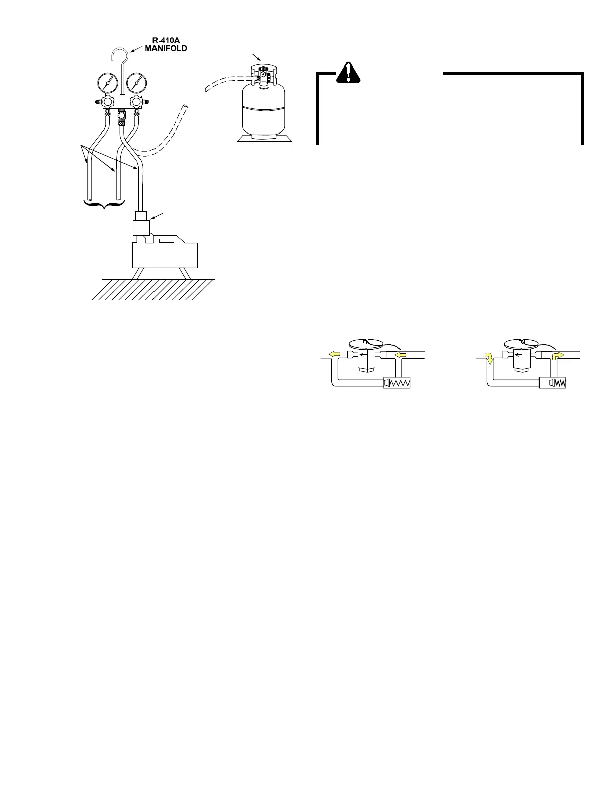
EVACUATION
3. If the vacuum pump is working properly, close the valve to
the vacuum thermocouple gauge and open the high and low
side valves to the high vacuum manifold set. With the valve
on the charging cylinder closed, open the manifold valve to
the cylinder.
4. Evacuate the system to at least 29 inches gauge before open-
ing valve to thermocouple vacuum gauge.
5. Connue to evacuate to a maximum of 250 microns. Close
valve to vacuum pump and watch rate of rise. If vacuum
does not rise above 1500 microns in three to ve minutes,
system can be considered properly evacuated.
6. If thermocouple vacuum gauge connues to rise and levels
o at about 5000 microns, moisture and non-condensables
are sll present. If gauge connues to rise a leak is present.
Repair and re-evacuate.
7. Close valve to thermocouple vacuum gauge and vacuum
pump. Shut o pump and prepare to charge.
S-103 CHARGING
WARNING
REFRIGERANT UNDER PRESSURE!
* Do not overcharge system with refrigerant.
* Do not operate unit in a vacuum or at negative
pressure.
Failure to follow proper procedures may cause
property damage, personal injury or death.
S-105B THERMOSTATIC EXPANSION VALVE
The expansion valve is designed to control the rate of liquid re-
frigerant ow into an evaporator coil in exact proporon to the
rate of evaporaon of the refrigerant in the coil. The amount of
refrigerant entering the coil is regulated since the valve responds
to temperature of the refrigerant gas leaving the coil (feeler
bulb contact) and the pressure of the refrigerant in the coil. This
regulaon of the ow prevents the return of liquid refrigerant to
the compressor.
The illustraon below shows typical heatpump TXV/check valve
operaon in the heang and cooling modes.
TXV VALVES
Some TXV valves contain an internal check valve thus eliminat-
ing the need for an external check valve and bypass loop. The
three forces which govern the operaon of the valve are: (1)
the pressure created in the power assembly by the feeler bulb,
(2) evaporator pressure, and (3) the equivalent pressure of the
superheat spring in the valve.
0% bleed type expansion valves are used on indoor and outdoor
coils. The 0% bleed valve will not allow the system pressures
(High and Low side) to equalize during the shut down period.
The valve will shut o completely at approximately 100 PSIG.
30% bleed valves used on some other models will connue to
allow some equalizaon even though the valve has shut-o com-
pletely because of the bleed holes within the valve. This type of
valve should not be used as a replacement for a 0% bleed valve,
due to the resulng drop in performance.
The bulb must be securely fastened with two straps to a clean
straight secon of the sucon line. Applicaon of the bulb to a
horizontal run of line is preferred. If a vercal installaon cannot
be avoided, the bulb must be mounted so that the capillary
tubing comes out at the top.
THE VALVES PROVIDED BY DAIKIN ARE DESIGNED TO MEET
THE SPECIFICATION REQUIREMENTS FOR OPTIMUM PRODUCT
OPERATION. DO NOT USE SUBSTITUTES.