11
• On a call for heat, the thermostat contacts close &
the control board receives 24 VAC on the W terminal.
• The control board microcomputer runs its self-check
routine.
• The control veries the limit switch is closed (24 VAC
on Pin 8 of the 12 Pin connector).
• The control veries that pressure switch circuit is
open (0 VAC on Pin 5).
• The control module performs a gas valve circuitry
check to verify gas valve relay state and presence of
voltage at the valve.
• The system will energize the Induced draft blower.
• The pre-purge period begins once the pressure
switch is detected closed (24 VAC on Pin 5).
• After the completion of pre-purge, the control will
energize the igniter.
• After completion of the ignitor warm-up period:
• The gas valve is energized.
• The ignitor is de-energized as soon as ame is
sensed.
• After 30 seconds the indoor blower is energized on
heating speed.
• When the thermostat is satised:
• The gas valve is de-energized.
• The inducer remains energized for the post purge
period (15 seconds).
• The indoor blower runs for the selected o delay pe-
riod (90 seconds by default, adjustable from 30 – 180
seconds).
To change the main blower speed in HEATING mode, follow
the following steps:
1. Press left or right button till LED displays “gA1 “(for
single stage HEATING). Press center button and LED
will display the selected speed number as Fxx (xx:
Blower speed number).
2. The control shall rotate available speed number
every time Left/Right switches are pressed. Table
below shows the available speeds for Low & High
heat mode.
3. When the center switch is pressed, the current
displayed speed shall be selected, and control shall
apply the newly selected speed in next heating call.
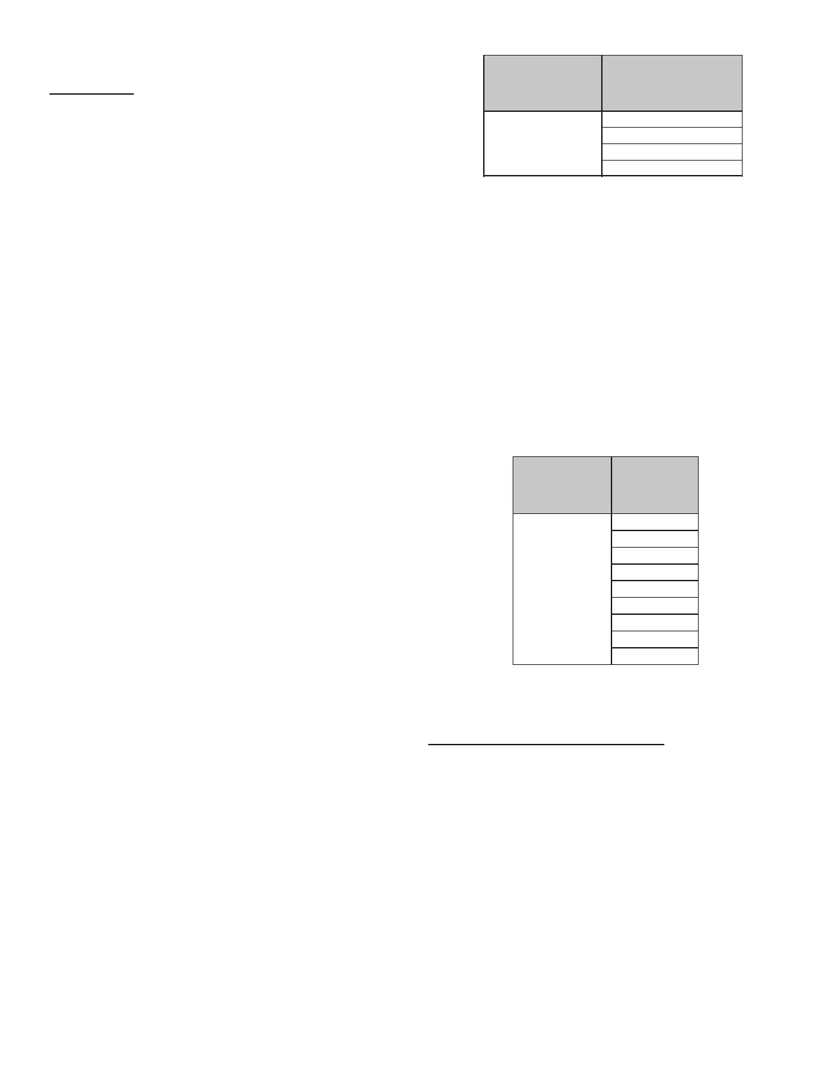
THERMOSTAT CALL AVAILABLE SPEEDS
W/W1
F01
F03
F04
F02 (DEFAULT)
To change the main blower speed in circulation mode, follow
the following steps:
1. Press the left or right switch until LED displays “FSd”.
Press the center switch and LED will display the
selected speed number as Fxx (xx: Blower speed
number from 1 to 9). F01 is the default speed for
circulation.
2. The control will rotate available speed number every
time left/right switches are pressed. All 9 speeds are
available for circulation.
3. When the center switch is pressed, the current
displayed speed will be selected, and control will
immediately apply that speed setting.
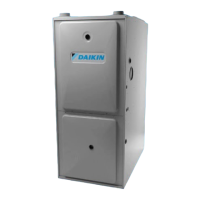
THERMOSTAT
CALL
AVAILABLE
SPEEDS
G
F01
F02
F03
(DEFAULT)
F04
F05
F06
F07
F08
F09
On a call for low stage cooling, the Y/Y1 or Y/Y1 and G ther-
mostat contacts close signaling the furnace control board
with 24 VAC on Y/Y1 or Y/Y1 and G terminals.
• The 7-Segment will display the cool mode:
• The compressor and condenser fan are energized.
• The circulator fan is energized at low cool speed after
a cool on delay. The electronic air cleaner will also be
energized.
• After the thermostat is satised, the compressor
is de-energized and the Cool Mode Fan O Delay
period begins.
• Following the Cool Mode Fan O Delay period, the
cool circulator and air cleaner relay are de-energized.