25
SERVICING
1. After turning o gas to furnace at the manual gas
shuto valve external to the furnace, remove burner
compartment door to gain access to the gas valve.
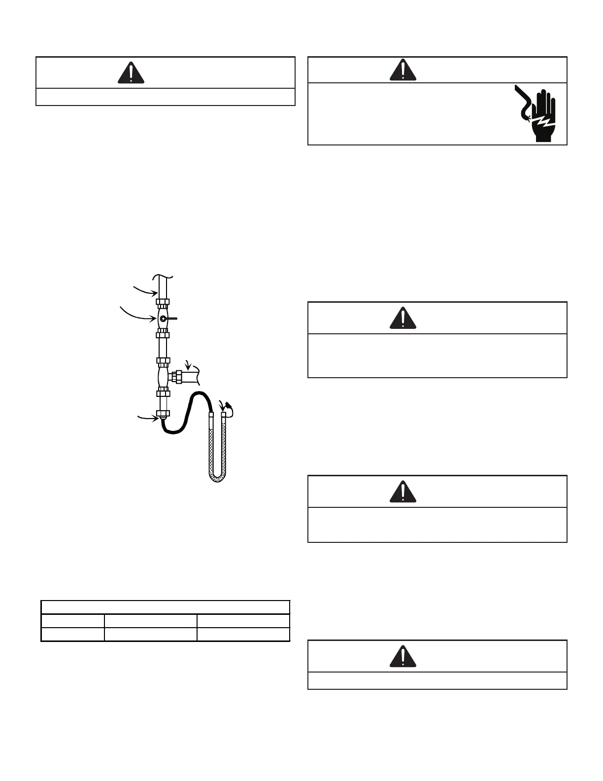
2. Connect a calibrated water manometer (or appropri-
ate gas pressure gauge) at either the gas valve inlet
pressure tap or the gas piping drip leg as shown in
the following gures. Refer to Measuring Gas Pres
gure for single stage
valve inlet pressure tap connections.
-
GAS LINE
GAS SHUTOFF VALVE
GAS LINE
TO FURNACE
DRIP LEG CAP
WITH FITTING
MANOMETER HOSE
MANOMETER
OPEN TO
ATMOSPHERE
3. Turn ON the gas and electrical power supply and
operate the furnace and all other gas consuming
appliances on the same gas supply line.
4. Measure furnace gas supply pressure with burners
ring. Supply pressure must be within the range
specied in the following table.
Natural Gas Minimum: 4.5" w.c. Maximum: 10.0" w.c.
Propane Gas Minimum: 11.0" w.c. Maximum: 13.0" w.c.
If supply pressure diers from above, make necessary ad-
justments to pressure regulator, gas piping size, etc., and/or
consult with local gas utility.
-
-
5. Disconnect manometer after turning o gas at manu-
al shuto valve. Reinstall plug before turning on gas
to furnace.
6. Turn OFF any unnecessary gas appliances started in
step 3.
7. Turn on gas to furnace and check for leaks. If leaks
are found, repair and then reinstall burner compart-
ment door.
8. Turn on electrical power and verify proper unit
operation.
Only small variations in gas pressure should be made by
adjusting the gas valve pressure regulator. The manifold
pressure must be measured with the burners operating. To
measure and adjust the manifold pressure, use the following
procedure.
1. After turning o gas to furnace at the manual gas
shuto valve external to the furnace, remove burner
compartment door to gain access to the gas valve.
2. Connect a calibrated water manometer (or appro-
priate gas pressure gauge) at the gas valve outlet
pressure tap. Refer to Measuring Gas Pressure: Sin-
gle Stage Valves gure for single stage valve outlet
pressure tap connections.