26
SERVICING
3. Turn ON the gas and electrical power supply and
operate the furnace.
4. Measure gas manifold pressure with burners ring.
Adjust manifold pressure using the table below.
The nal manifold pressure must not vary more than ± 0.3”
w.c. from the above specied pressures. Any necessary ma-
jor changes in gas ow rate should be made by changing the
size of the burner orice.
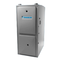
5. White-Rodgers 36J22 Valves:
a. Back outlet pressure test screw (inlet/outlet pres-
sure boss) out one turn (counterclockwise, not
more than one turn).
b. Attach a hose and manometer to the outlet pres-
sure outlet pressure boss.
c. Turn ON the gas supply.
d. Turn on power and close thermostat “R” and “W”
contacts to provide a call for low stage heat.
e. Measure the gas manifold pressure with burners
ring. Adjust manifold pressure using the Mani
fold Gas Pressure table shown below.
f. Remove regulator cover screw from the outlet
pressure regulator adjust tower and turn screw
clockwise to increase pressure or counterclock-
wise to decrease pressure. Replace regulator
cover screw.
g. Turn o all electrical power and gas supply to the
system.
h. Remove the manometer hose from the hose barb
tting or outlet pressure boss.
i. Turn outlet pressure test screw in to seal pres-
sure port (clockwise, 7 in-lb minimum).
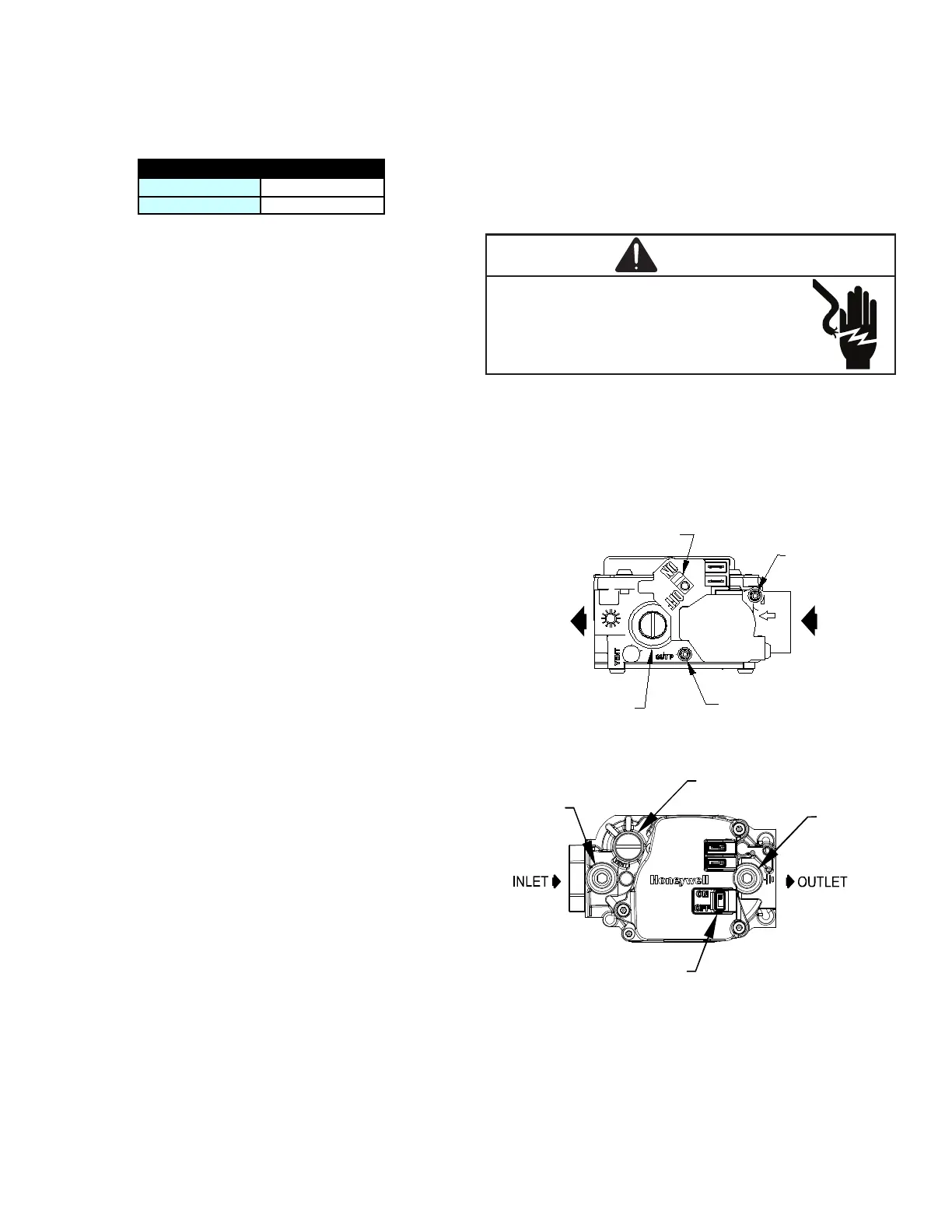
6. Honeywell VR8215 Valve:
a. Remove the outlet pressure boss plug. Install an
1/8” NPT hose barb tting into the outlet pressure
tap.
b. Attach a hose and manometer to the outlet pres-
sure barb tting.
c. Turn ON the gas supply.
d. Turn on power and close thermostat “R” and “W”
contacts to provide a call for low stage heat.
e. Measure the gas manifold pressure with burners
ring. Adjust manifold pressure using the Mani-
fold Gas Pressure table shown below.
f. Remove regulator cover screw from the outlet
pressure regulator adjust tower and turn screw
clockwise to increase pressure or counterclock-
wise to decrease pressure. Replace regulator
cover screw.
g. Turn o all electrical power and gas supply to the
system.
h. Remove the manometer hose from the hose barb
tting or outlet pressure boss.
i. Remove the 1/8” NPT hose barb tting from the
outlet pressure tap. Replace the outlet pressure
boss plug and seal with a high quality thread
sealer.
-
-
7. Turn on gas to furnace and check for leaks. If leaks
are found, repair and then reinstall burner compart-
ment door.
8. Turn on electrical power and verify proper unit
operation.
Pressure Regulator
Adjustment
(Under Cap Screw)
Gas Valve
On/Off
Selector
Switch
INLET
OUTLET
Inlet Pressure
Tap
Outlet Pressure
Tap
Gas Valve On/Off
Selector Switch
Inlet
Pressure
Ta p
Pressure Regulator
(under cap screw)
Outlet
Pressure
Ta p