16 | Unit installation
Installer and user reference guide
60
FAA71+100BUV1B
Split system air conditioner
4P654517-1 – 2021.03
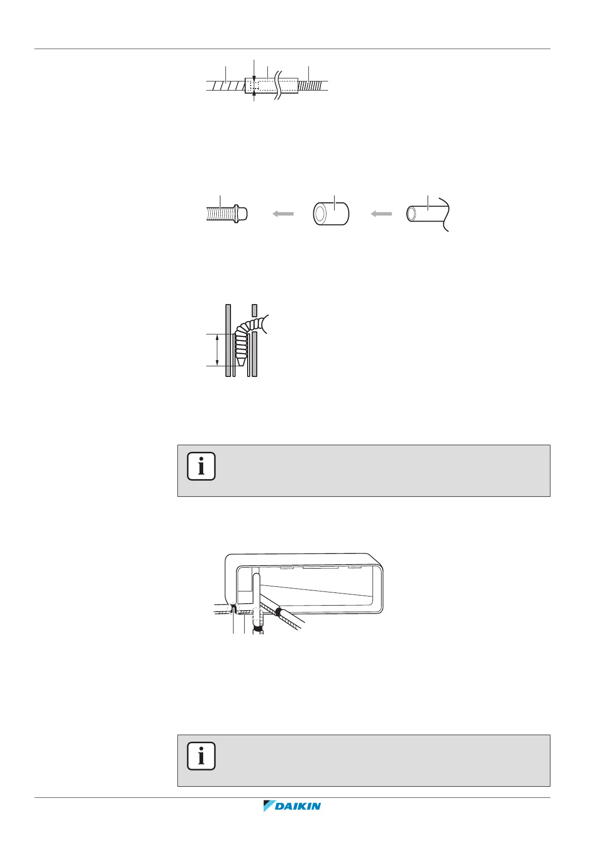
a Drain hose supplied with the indoor unit
b Heat insulation tube (field supply)
c Extension drain hose (field supply)
▪ Rigid polyvinyl chloride pipe. When connecting a rigid polyvinyl chloride pipe
(nominal Ø13mm) directly to the drain hose as with embedded piping work, use
a field supplied drain socket (nominal Ø13mm).
a Drain hose supplied with the indoor unit
b Drain socket with nominal Ø13mm (field supply)
c Rigid polyvinyl chloride pipe (field supply)
▪ Insert the drain hose in the drain pipe as shown in the following figure, so it will
NOT be pulled out of the drain pipe.
▪ Condensation. Take measures against condensation. Insulate the complete drain
piping in the building.
To connect the piping on right side, right-back, or right-bottom
INFORMATION
The factory default is right-side piping. For left-side piping, remove the piping from
the right side and install it on the left side.
1 Attach the drain hose with adhesive vinyl tape to the bottom of the
refrigerant pipes.
2 Wrap the drain hose and the refrigerant pipes together using insulation tape.
A Right-side piping
B Right-bottom piping
C Right-back piping
a Remove the pipe port cover here for right side piping
b Remove the pipe port cover here for right-bottom piping
To connect the piping on left side, left-back, or left-bottom
INFORMATION
The factory default is right-side piping. For left-side piping, remove the piping from
the right side and install it on the left side.
 Loading...