25 | Technical data
Installer and user reference guide
84
FAA71+100BUV1B
Split system air conditioner
4P654517-1 – 2021.03
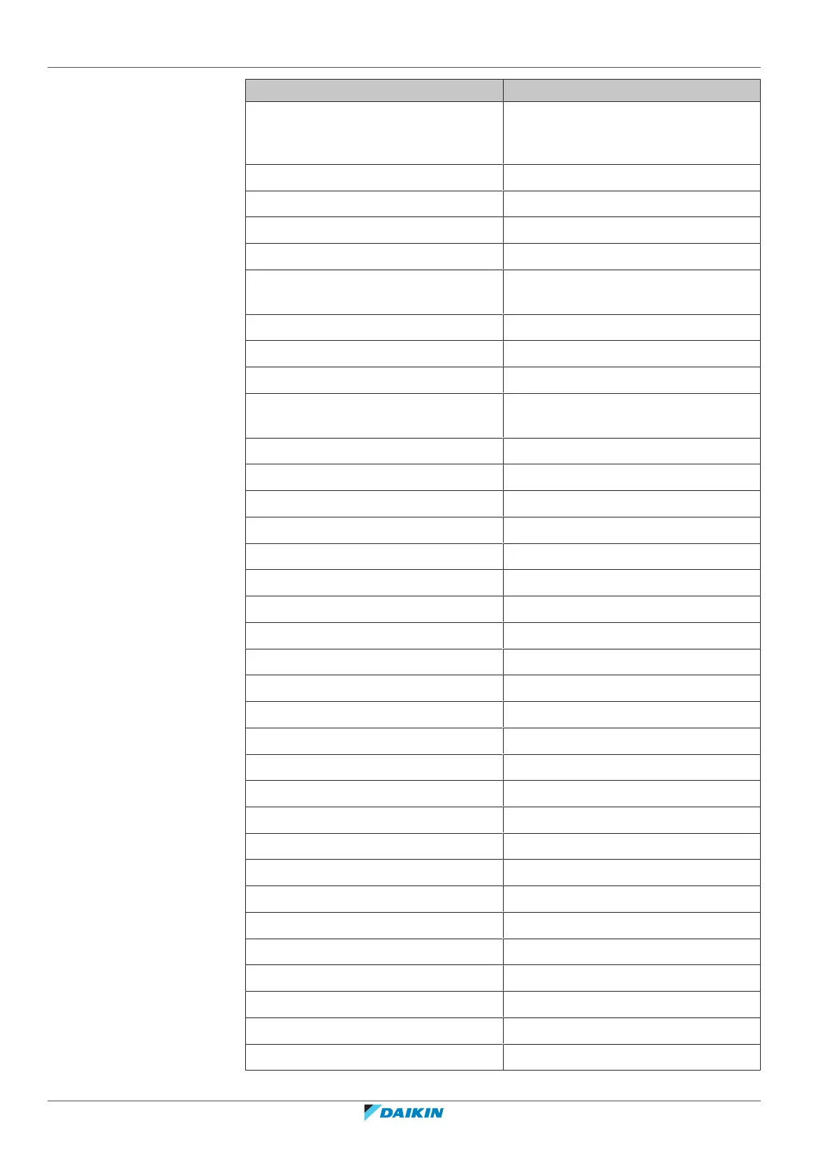
Symbol Meaning
AC*, CN*, E*, HA*, HE*, HL*, HN*, HR*,
MR*_A, MR*_B, S*, U, V, W, X*A,
K*R_*, NE
Connection, connector
D*, V*D Diode
DB* Diode bridge
DS* DIP switch
E*H Heater
FU*, F*U, (for characteristics, refer to
PCB inside your unit)
Fuse
FG* Connector (frame ground)
H* Harness
H*P, LED*, V*L Pilot lamp, light emitting diode
HAP Light emitting diode (service monitor
green)
HIGH VOLTAGE High voltage
IES Intelligent eye sensor
IPM* Intelligent power module
K*R, KCR, KFR, KHuR, K*M Magnetic relay
L Live
L* Coil
L*R Reactor
M* Stepper motor
M*C Compressor motor
M*F Fan motor
M*P Drain pump motor
M*S Swing motor
MR*, MRCW*, MRM*, MRN* Magnetic relay
N Neutral
n=*, N=* Number of passes through ferrite core
PAM Pulse-amplitude modulation
PCB* Printed circuit board
PM* Power module
PS Switching power supply
PTC* PTC thermistor
Q* Insulated gate bipolar transistor (IGBT)
Q*C Circuit breaker
Q*DI, KLM Earth leak circuit breaker
Q*L Overload protector
 Loading...